




Aluminum 5052: Performance and Machining Characteristics of EN AW-5052 | 2026 Complete Engineering & Procurement Guide
Published on Friday, 25. September 2026
Content Guide:Learn Aluminum 5052 / EN AW‑5052 characteristics: mechanical properties, temper, CNC machining parameters, tolerances, DFM tips, common defects and comparison with 6061 and 7075 aluminum alloys.
EN AW-5052 is a wrought Al-Mg alloy in the 5xxx series. Its engineering value is not maximum strength; it is the combination of corrosion resistance, ductility, cold-work strengthening, weldability, and predictable sheet/plate fabrication behavior. For CNC machining, however, that same ductility can produce long chips, built-up edge, burrs, and local deformation unless tooling, workholding, thermal control, and inspection are designed around the material.
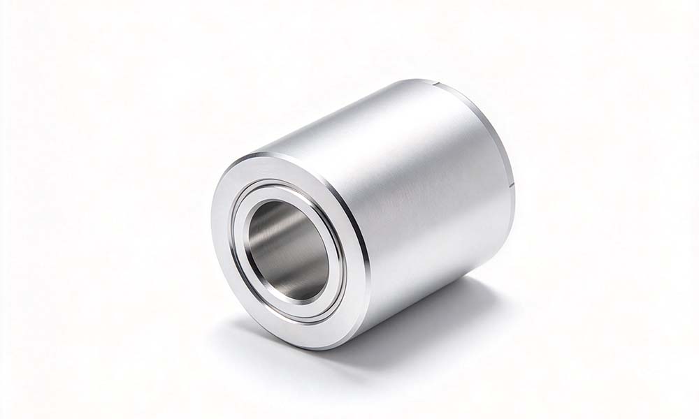
Article overview. This guide answers the questions that matter on a production drawing: what EN AW-5052 is, how its temper changes mechanical behavior, why it machines differently from 6061 and 7075, how to establish safe starting cutting data, how to control tolerance and surface finish, which secondary processes are compatible, what DFM rules reduce risk, how to diagnose common defects, how cost is really formed, and what a B2B buyer should require from a CNC supplier.
Evidence note: Alloy designation and chemistry are aligned to EN 573-3:2026 and the Aluminum Association designation system. Mechanical-property requirements for sheet, strip and plate are governed by the applicable product standard and product form; typical property values shown here are clearly identified as typical rather than design allowables. Machining parameters are engineering starting windows, not universal “certified” settings. Always validate them against the actual tool, machine, holder, coolant delivery, material temper, stock condition and feature geometry.
Contents
What Is EN AW-5052 Aluminum?
Chemical & Physical Properties
Mechanical Performance by Temper
Core Functional Advantages & Limitations
CNC Machining Mechanics of 5052
Optimized 2026 CNC Machining Parameters
5052 vs 6061 vs 7075
Tolerance & Surface Finish Capability
Surface Treatment, Welding & Assembly
Typical CNC Machined Parts
When to Choose 5052
When Not to Use 5052
2026 CNC Machining Cost Factors
DFM Guidelines
Common Machining Defects & Diagnosis
Selecting a 5052 CNC Machining Supplier
Prototype vs Small Batch vs Mass Production
Professional Factory Workflow
FAQ
Standards & Authoritative Sources
EN AW-5052 is the European wrought-alloy designation for the 5xxx-series aluminum alloy commonly identified in North America as AA 5052 / UNS A95052. The alloy family is based on aluminum with magnesium as the principal alloying addition; chromium is also present within the specified range. EN 573-3:2026 defines the chemical-composition limits for wrought aluminum alloys, while ANSI H35.1/H35.1M defines the alloy and temper designation system. The current European chemistry standard was published as EN 573-3:2026 on 18 March 2026. [1][2]
For procurement, the important distinction is that “5052” identifies the alloy, while O, H32, H34, H36, H38 and related designations identify the material temper. Temper is not a cosmetic suffix. It records the metallurgical state and therefore changes tensile strength, yield strength, elongation, forming behavior and machining response.
5052 is strengthened primarily through solid-solution effects and cold work, rather than precipitation hardening. This places it in the non-heat-treatable 5xxx family. An H temper therefore reflects work hardening rather than a T6-type solution-treatment-and-aging sequence. A CNC shop cannot “make 5052 into T6” in the way it can with 6061 or 7075. Annealing can reduce the work-hardened condition, but that is a different operation and must be specified deliberately.
The manufacturing consequence is significant. If a drawing specifies H32, replacing it with O because “it is easier to machine” changes the material condition and can change the part's stiffness, strength and forming behavior. Likewise, switching between H32 and H34 without engineering approval is not a harmless sourcing substitution.
Temper | Metallurgical meaning | Typical engineering trend | Machining / forming consequence |
|---|---|---|---|
O | Annealed | Lowest strength, highest ductility among these common conditions | Excellent formability but relatively low rigidity; thin sections can move under clamping or cutting forces. |
H32 | Strain hardened and stabilized | Moderate strength with useful ductility | Often a practical balance for formed housings and machined components where strength and manufacturability both matter. |
H34 | Higher degree of strain hardening, stabilized | Higher strength, lower elongation than H32 | Greater resistance to deformation in service, but less forming margin and typically more cutting-edge load. |
H36 | More heavily strain hardened, stabilized | Higher strength and hardness | Useful where strength matters more than deep forming; thin-wall cutting still requires careful workholding. |
H38 | Heavily strain hardened, stabilized | Highest strength among the listed common tempers | Lowest ductility of the group; good for formed sheet where higher strength is required, but not automatically the best choice for CNC geometry. |
Temper definitions are standardized; exact product-property limits depend on the applicable product standard, product form and thickness. The practical descriptions above are engineering interpretations, not replacements for the material certificate or governing specification. [1][3]
The following composition is the EN AW-5052 chemistry listed in EN 573-3:2026. Values are mass fractions. “Remainder” means aluminum makes up the balance after specified alloying elements and impurities are accounted for. [1]
Element | EN AW-5052 limit, wt.% | Why it matters to engineering |
|---|---|---|
Si | ≤ 0.25 | Kept low relative to cast Al-Si alloys; chemistry control helps maintain the intended wrought-alloy behavior. |
Fe | ≤ 0.40 | Iron-bearing intermetallics can affect local machinability, tool wear and surface response when chemistry approaches limits. |
Cu | ≤ 0.10 | Low copper contributes to 5052's good corrosion-resistance profile compared with Cu-rich aluminum alloys. |
Mn | ≤ 0.10 | Minor addition; not the principal strengthening mechanism of this alloy. |
Mg | 2.2–2.8 | Primary alloying element; supports solid-solution strengthening and corrosion-resistant 5xxx-series behavior. |
Cr | 0.15–0.35 | Contributes to microstructure control and corrosion-resistant alloy behavior. |
Zn | ≤ 0.10 | Controlled as an impurity/minor addition in this alloy. |
Ti | ≤ 0.10 | Grain-refining additions may occur within the standard limit depending on production route. |
Other, each | ≤ 0.05 | Controls residual elements outside the principal chemistry. |
Other, total | ≤ 0.15 | Controls combined residual-element content. |
Al | Remainder | Base metal. |
Physical values below are typical reference data, not purchase acceptance limits. The exact value used in simulation, thermal analysis or design release should come from the material producer's certificate or a qualified database appropriate to the product form and temperature range. MatWeb, drawing on Aluminum Association data for the cited typical values, lists density around 2.68 g/cm3, modulus of elasticity about 70.3 GPa, thermal conductivity about 138 W/m·K and a melting range of roughly 607–649 °C for typical wrought product. [4]
Property | Typical reference value | CNC / design consequence |
|---|---|---|
Density | ≈ 2.68 g/cm3 | Low mass compared with steels; raw-stock weight is not usually the dominant machining-cost factor for small parts. |
Elastic modulus | ≈ 70.3 GPa | Aluminum is much less stiff than steel; thin walls and long spans can deflect even when dimensional cutting accuracy is excellent. |
Thermal conductivity | ≈ 138 W/m·K | Heat can move rapidly into the workpiece and fixture, but high conductivity does not eliminate local cutting-zone heating. |
CTE, 20–100 °C | ≈ 23.8 µm/m·K | Temperature changes can move inspection results. Thermal equilibration matters on tight-tolerance work. |
Melting range | ≈ 607–649 °C | Relevant to welding and thermal processing; it is not a machining temperature target. |
Poisson's ratio | ≈ 0.33 | Useful for mechanical analysis; it does not predict machining accuracy by itself. |
The most common mistake in aluminum procurement is treating an alloy designation as if it uniquely defines mechanical properties. It does not. Product form, thickness and temper matter. EN 485-2 governs mechanical properties for wrought sheet, strip and plate for general engineering applications; the standard framework explicitly links chemistry to EN 573-3 and temper designation to EN 515. In 2026, European standards are transitioning to a newer EN 485-2 edition, so a purchase order should cite the exact edition/product standard required by the project rather than relying on an informal “5052” label. [5]
Temper | Typical ultimate tensile strength | Typical yield strength | Typical elongation trend | Engineering interpretation |
|---|---|---|---|---|
5052-O | ≈ 195 MPa | ≈ 90 MPa | ≈ 25% | Highly ductile and formable; lower strength and lower resistance to cutting-induced deformation. |
5052-H32 | ≈ 230 MPa | ≈ 195 MPa | ≈ 12% | Balanced condition for many general engineering applications. |
5052-H34 | ≈ 260 MPa | ≈ 215 MPa | ≈ 10% | More strength and hardness, less ductility. |
5052-H36 | ≈ 275 MPa | ≈ 240 MPa | ≈ 8% | Higher strength with reduced forming margin. |
5052-H38 | ≈ 290 MPa | ≈ 255 MPa | ≈ 7% | Highest strength in this common subset, with the least ductility. |
These are typical reference figures derived from Aluminum Association data as reproduced in engineering material databases, not a substitute for EN/ASTM certificate values. Specification minima/maxima vary with thickness and product form. [4][6]
Cold work raises dislocation density and therefore yield strength and hardness. In simple machining terms, this can make the cutting edge encounter a somewhat more resistant surface layer. At the same time, 5052 remains a ductile alloy. The result is not “hard machining” in the tool-life sense associated with hardened tool steels; it is a tendency toward sticky material behavior, burrs and local deformation when the cutting edge is dull, the chip is too thin, or the workpiece is inadequately supported.
For procurement, the practical rule is to specify temper together with thickness and product form. For machining trials, the first samples should be made from the same temper and, ideally, the same supplier/heat-lot strategy intended for production. A process stabilized on 5052-H32 should not automatically be assumed stable on H38.
WHAT: 5052 has good general corrosion resistance and is widely used where atmospheric and marine-adjacent exposure is a concern. HOW: the aluminum surface forms a protective oxide film, while the low-copper Al-Mg chemistry supports the 5xxx corrosion-resistance profile. WHY IT MATTERS: housings, covers, panels and fixtures can sometimes meet environmental requirements without relying on a thick decorative coating. Boundary: “marine-grade” is not a universal synonym for 5052. ASTM B928/B928M is a separate specification for high-magnesium aluminum products intended for marine service and similar environments. Material certificate and applicable marine specification still govern. [7]
WHAT: 5052 retains useful elongation, especially in O and lower H tempers. HOW: the solid-solution strengthened Al-Mg matrix accommodates plastic deformation better than many high-strength precipitation-hardened alloys. CONSEQUENCE: sheet-based geometries can be formed and thin sections can tolerate some handling without brittle fracture. Boundary: high ductility can become a machining problem when aggressive clamping or a heavy finishing pass pushes a thin wall out of position.
WHAT: H tempers increase strength through controlled strain hardening. CONSEQUENCE: service strength can be raised without precipitation aging. Boundary: because this is not a T6-type alloy, heat treatment after machining is not a normal way to recover or increase strength; any annealing or thermal exposure can change temper and dimensional behavior.
WHAT: aluminum's modulus is around 70 GPa. WHY IT MATTERS: a 5052 part can be cut to a dimension accurately at the cutting edge and still move after unclamping. Consequence: rigidity comes from geometry, support strategy and assembly design—not from specifying a tighter machining tolerance alone.
Important correction to a common claim: “non-heat-treatable” does not mean “zero thermal distortion.” 5052 still has a relatively high coefficient of thermal expansion, and machining generates heat. The actual advantage is that 5052 does not depend on a precipitation-hardening heat-treatment sequence that could introduce an additional post-machining dimensional change. Thermal control during cutting and inspection still matters.
5052 is machinable, but its machining response is different from the classic “free-cutting” behavior that many buyers associate with 6061. The important variables are chip thickness, cutting-edge sharpness, heat, toolpath engagement and workpiece support.
5052 can produce long, continuous chips. When the chip evacuation path is poor, those chips can wrap around the tool, workholding or part. Recirculating chips can also be re-cut, which raises heat and degrades surface finish. The engineering response is positive-rake geometry, adequate chip space, a cutting edge sharp enough to shear rather than rub, and coolant/air delivery aimed at removing chips from the cutting zone.
Built-up edge occurs when work material adheres to the cutting edge. This is especially relevant to sticky ductile materials such as aluminum. The immediate symptoms are changing cutting forces, torn or smeared surface finish, burr growth and unstable dimensions. Sandvik Coromant's technical guidance notes that BUE is associated with low cutting-zone temperature and sticky materials including aluminum, and lists increasing cutting speed/feed or improving cutting-fluid use among troubleshooting actions. [8]
For 5052, a practical shop response is usually to check the tool first: edge sharpness, flute geometry, chip evacuation and coating compatibility. A dull tool that rubs instead of cuts creates a feedback loop: more heat → more adhesion → worse finish → more rubbing.
Thin 5052 walls are vulnerable because of the alloy's ductility and aluminum's relatively low elastic modulus. During roughing, the wall is supported by surrounding stock. Once one side is opened, the remaining wall becomes flexible. A final pass that looks “light” in chip load can still produce a dimensional shift if the cutter engages too much unsupported material.
The strongest control is not a magic feed value. It is geometry + workholding + toolpath sequence. Leave support stock, machine symmetric features where possible, avoid excessive stick-out, use multiple finishing passes, and release clamping stress gradually rather than trapping a flexible wall under high clamp load.
High spindle speed is not automatically high temperature. Heat depends on cutting speed, chip thickness, tool geometry, engagement, lubrication and how efficiently the chip carries heat away. The goal is to keep the edge cutting, not rubbing. For 5052, excessive speed without enough chip load can create rubbing; insufficient speed in the wrong geometry can encourage BUE. That is why a supplier should tune speed and feed as a pair rather than changing spindle speed alone.
Burrs are strongly affected by ductility, edge direction, tool wear, exit geometry and final-pass strategy. In 5052, burrs commonly increase when a tool approaches the edge with insufficient support or when a worn cutter plastically pushes material rather than shearing it. Small chamfers or controlled edge breaks are often more robust than specifying “zero burr,” which is a visually ambiguous acceptance requirement.
Parameter disclaimer: there is no single standards-defined “5052 CNC cutting speed.” Cutting data are process parameters, not material certification values. The ranges below are deliberately presented as starting windows for sharp solid-carbide aluminum tooling. They must be verified against tool-maker recommendations, machine power, spindle maximum, holder runout, coolant delivery and feature geometry. For actual production, the tool manufacturer's calculator/data sheet should take precedence.
Operation | Tool concept | Why | Typical process-control priority |
|---|---|---|---|
Rough milling | 2–3 flute polished or aluminum-specific carbide; high helix when appropriate | Large chip space and sharp geometry support chip evacuation. | Stable chip load, avoid recutting and use adaptive/HEM engagement where machine/tooling supports it. |
Finish milling | 2–3 flute sharp carbide finisher, preferably polished for aluminum | Low radial engagement and a clean edge reduce rubbing and smearing. | Tool runout, wall support, consistent stock allowance. |
Face milling | Aluminum-geometry insert cutter or suitable carbide cutter | Positive geometry can reduce cutting forces and BUE tendency. | Keep the cutter loaded enough to cut cleanly; evacuate long chips. |
Drilling | Sharp geometry designed for aluminum; carbide or HSS depending diameter, depth and machine stability | Point geometry and flute space influence chip evacuation. | Peck strategy for deep holes, coolant and chip exit. |
Turning | Positive-rake polished carbide / aluminum-grade insert | Low cutting force and anti-adhesion behavior are important. | Maintain adequate feed to prevent rubbing; keep chips controlled. |
For a modern VMC with rigid workholding and sharp aluminum-specific solid-carbide tooling, a practical first trial can start in the following neighborhood. This is a process-development window, not a material standard:
Operation | Surface speed Vc | Feed per tooth fz | Radial engagement ae | Axial depth ap |
|---|---|---|---|---|
Roughing / adaptive milling | ≈ 300–500 m/min | ≈ 0.06–0.12 mm/tooth | ≈ 5–20% of tool diameter | ≈ 0.5–1.5×D where tool rigidity permits |
Conventional pocket/side roughing | ≈ 250–450 m/min | ≈ 0.05–0.12 mm/tooth | ≈ 20–50% of tool diameter | Geometry-dependent; keep radial load stable |
Wall finishing | ≈ 350–550 m/min | ≈ 0.02–0.06 mm/tooth | ≈ 0.05–0.25 mm | Prefer several light passes for thin walls |
Example spindle-speed calculation:
n (rpm) = 1000 × Vc (m/min) ÷ (π × D (mm))
Example feed calculation:
Vf (mm/min) = n × z × fz
As an illustration, a 10 mm three-flute tool at 450 m/min calculates to approximately 14,300 rpm. At 0.08 mm/tooth, the corresponding feed is approximately 3,430 mm/min. These are arithmetic examples, not a promise that every 10 mm cutter and every machine should be run there. Manufacturer limits, holder balance, runout, coolant delivery, tool length and machine spindle capability remain decisive.
Flood coolant, targeted high-flow coolant or air-assisted chip evacuation can all work, depending on the machine and geometry. The objective is to keep chips from being re-cut and to reduce adhesion. A very high coolant-pressure number should not be treated as a universal requirement; what matters is whether the delivery actually clears chips from the engagement zone without creating an unsafe or unstable process.
Roughing | Finishing |
|---|---|
Optimize material removal rate while keeping the cutter fully loaded enough to shear. | Optimize edge sharpness, runout, wall support, and stock consistency. |
Prefer stable engagement over sudden full-slot shocks where geometry permits. | Use smaller radial engagement; avoid a finishing pass that is so light the tool begins to rub. |
Prioritize chip evacuation and machine-power stability. | Prioritize thermal stabilization and consistent cutter entry/exit. |
Harvey Tool publishes aluminum-specific 2–3 flute and variable-helix carbide tooling families, while Kennametal publishes aluminum-specific positive-geometry insert grades designed to resist BUE and reduce burrs. These manufacturer offerings support the general tool-selection principle here: use geometry and edge preparation intended for aluminum rather than treating 5052 as generic metal. [9][10]
Factor | 5052 | 6061-T6/T651 | 7075-T6/T651 |
|---|---|---|---|
Strengthening mechanism | Non-heat-treatable; solid-solution + cold work | Heat-treatable; precipitation strengthened | Heat-treatable; precipitation strengthened |
Corrosion resistance | Generally very good | Good | Good but more engineering caution is needed in aggressive/stress-corrosion environments |
Machining behavior | Ductile; can be gummy; BUE/burr control important | Generally predictable and widely machined | Generally excellent strength-to-weight, with more tool load than 5052 but good CNC machinability |
Rigidity | Low aluminum modulus; geometry controls deflection | Similar elastic modulus to 5052 | Similar elastic modulus to other aluminum alloys; higher strength does not mean higher stiffness |
Typical strength level | Moderate | Moderate to high depending temper | High to very high |
Formability | Strong advantage, especially lower tempers | Good in suitable tempers, less formable than 5052 in T6 condition | Limited compared with 5052 in high-strength tempers |
Weldability | Good in many conventional processes | Good; heat-affected-zone strength reduction must be considered | More difficult to weld; post-weld property loss and cracking/corrosion considerations can be significant |
Dimensional behavior | Can move due to low stiffness, temper and residual stress; no “zero thermal distortion” advantage | Heat-treatment condition and residual stress matter; T651-type stress relief can be relevant | High-strength plate and residual stress require careful machining strategy |
Typical use logic | Corrosion-resistant housings, panels, brackets, marine-adjacent structures, formed parts, moderate-load thin-wall components | General precision components, brackets, structural parts, machined housings | High-strength structural parts, aerospace/transport components, highly loaded hardware |
When it is usually not the first choice | High-load, high-hardness or highly wear-sensitive components | Very high-strength applications where 7075-type strength is justified | Highly formed/welded corrosion-exposed parts where a more formable/weldable 5xxx alloy fits better |
For reference, typical 6061-T6 data are around 2.70 g/cm3 density and 68.9–70.3 GPa elastic modulus, while 7075-T6 is around 2.81 g/cm3 with modulus around 71.7 GPa. The important design point is that the elastic moduli are broadly similar: switching from 5052 to 7075 does not transform a flexible thin wall into a rigid one. What changes dramatically is allowable stress. [11][12]
There is no single “5052 machining tolerance” that applies to every part. The achievable result is a system property influenced by geometry, stock, workholding, cutting conditions, temperature, machine condition and measurement uncertainty.
Factor | Mechanism | Control strategy |
|---|---|---|
Temper | Changes yield strength, hardness and deformation response. | Specify temper on PO and verify the certificate before machining. |
Tool condition | Wear and adhesion change effective tool size and cutting force. | Tool-life limits, tool inspection and stable replacement criteria. |
Workholding | Clamping can elastically or plastically deform thin sections. | Use distributed support, controlled clamp force and datum-based fixturing. |
Thermal expansion | 5052 expands measurably with temperature. | Keep machine/part/inspection temperature controlled and allow thermal equalization. |
Geometry | Low modulus causes deflection and springback in thin walls and long spans. | Design ribs/supports, sequence operations, leave support stock where possible. |
Machine & spindle | Runout, thermal growth and axis geometry affect feature location and size. | Routine calibration, warm-up procedure and process capability checks. |
Inspection | Gauge repeatability and temperature can become part of the measured variation. | Use calibrated CMM/gauges, controlled setup, and a defined measurement method. |
Use individual dimensional and geometric tolerances for function-critical features. General tolerances should be used only when they are explicitly accepted by the drawing. ISO 2768 provides a framework for general tolerancing of linear and angular dimensions, while ISO 1101 defines the symbol language and rules for geometrical specification. ISO 2768 is also being revised in 2026, so engineering drawings should identify the intended standard edition where contractual interpretation matters. [13][14]
For geometric control, flatness, parallelism, perpendicularity and position are often more useful than simply tightening all size tolerances. Example: if a 5052 mounting plate must bolt to two mating structures, controlling the datum-related position and the interface flatness can deliver better assembly performance than arbitrarily reducing every hole-size tolerance.
A good 5052 surface finish comes from stable cutting rather than excessive “polishing by cutter.” The key variables are sharpness, tool runout, radial engagement, finishing stock, feed per tooth, vibration, coolant and the absence of built-up edge. Surface texture should be specified with a recognized parameter and evaluation method. ISO 21920-2:2021 defines profile surface-texture parameters; ISO 21920-1:2021 covers surface-texture indication, with ISO working documents currently under revision in 2026. [15][16]
Do not specify an extremely low Ra simply because the cosmetic appearance is important. Very fine roughness may require additional finishing operations, increased tool wear control, more cleaning and more inspection time. A functional surface should be specified to the level required by sealing, sliding, optical, cosmetic or contamination-control needs.
5052 is generally compatible with anodizing. The Aluminum Anodizers Council's alloy reference lists 5052 among 5xxx alloys used for anodizing, noting good protective coating behavior for the alloy family. [17] For production, however, the final appearance is affected by alloy chemistry, temper, surface preparation, lot variation, blasting/brushing direction and anodizing process. A “clear anodized” color match should therefore be treated as a process-control requirement, not just a finish-name requirement.
Brushing is often a practical cosmetic finish for housings and panels because it creates a directional texture that is easier to control visually than a mirror polish. Polishing can improve appearance but may reveal rolling or machining marks that were not obvious in a mill finish. The supplier should approve a representative sample when appearance is critical.
Aluminum is naturally protected by an oxide film. When a specification calls for a conversion coating, use the actual coating standard and process name rather than borrowing stainless-steel “passivation” language. The objective may be corrosion protection, electrical conductivity, paint adhesion or regulatory compliance, and the correct process depends on the application.
5052 has good weldability in many conventional processes. However, welding can change local geometry and, depending on the starting temper and thermal cycle, can reduce the strength associated with a work-hardened condition in the heat-affected region. For a machined-and-welded assembly, the drawing should make clear whether post-weld machining is required and where functional datums are established.
The best way to understand 5052's application range is by geometry and load case rather than by industry name alone.
Part type | Why 5052 fits | Design / machining watch-out |
|---|---|---|
Corrosion-resistant equipment housings | Good atmospheric corrosion resistance, low density and good forming behavior. | Large flat walls can distort; include ribs, returns or controlled support features. |
Automation and robotic brackets | Useful for moderate-load brackets where low weight and corrosion resistance matter. | Do not treat strength as equivalent to 7075; check cyclic load and joint stiffness. |
Marine/coastal components | Useful corrosion-resistant alloy family. | Verify whether the procurement specification requires a dedicated marine product standard such as ASTM B928/B928M. |
Medical/laboratory structural parts | Low density, cleanable surfaces and corrosion resistance can be valuable. | Material, finish and cleaning requirements must be application-specific; avoid assuming medical compliance from material grade alone. |
Heat-dissipation parts | Thermal conductivity is useful for housings and moderate heat-spreading duties. | Thermal conductivity alone does not make 5052 an optimized heat-sink alloy; geometry and mating resistance can dominate. |
Precision thin-wall non-high-load parts | Ductility and low density are attractive. | Low stiffness means support strategy and tolerance hierarchy are critical. |
A sound selection decision starts with the service environment and functional load, then works backward to manufacturing.
Especially where the part faces humid, outdoor or coastal atmospheric exposure and the design load is moderate. Confirm the exact environmental standard if the part is safety-critical or permanently exposed to seawater.
O prioritizes ductility/forming; H32/H34 often offer a balance; H36/H38 move further toward strength and away from forming margin. The correct temper depends on the part, not the machining supplier's convenience.
5052 can be machined thin, but “can be machined thin” is not the same as “will hold any tolerance at any wall thickness.” The drawing, fixture and toolpath must agree on how the wall is supported.
Anodizing and cosmetic brushing can be practical, but the appearance target should be specified with samples or objective acceptance criteria where necessary.
Professional material selection includes knowing when not to select the material.
Requirement | Why another material may make more sense | Possible direction |
|---|---|---|
Very high static strength | 5052 is a moderate-strength alloy and cannot be precipitation hardened like 6061/7075. | Evaluate 6061, 6082, 7075 or another qualified structural alloy. |
High surface hardness / wear resistance | 5052 is relatively soft and ductile. | Consider a harder alloy, steel, tool steel or engineered surface treatment. |
Large complex high-volume casting geometry | Machining a large billet into deep cavities can create high material waste and cycle time. | Evaluate casting/forging + finish machining where annual volume justifies tooling. |
Extremely high stiffness at low thickness | Changing from 5052 to a stronger aluminum alloy does not materially change elastic modulus enough to solve a stiffness problem by itself. | Change geometry, add ribs, increase thickness or consider a different material system. |
High-load aerospace-style strength-to-weight requirement | 5052 may not provide the required allowable stress. | Evaluate aerospace-qualified alloys and temper/product standards appropriate to the design. |
For B2B procurement, the relevant number is total landed cost, not the raw material line or an advertised hourly rate.
Cost factor | What drives it | How buyers can reduce avoidable cost |
|---|---|---|
Raw material | Alloy, temper, form, thickness, sheet/plate size and certification. | Specify the minimum qualified product form and avoid unnecessary oversize stock. |
Programming & process planning | Number of setups, multi-axis work, complicated datums, thin walls and inspection requirements. | Provide good CAD + drawing data and permit sensible datums / stock where function allows. |
Machining time | Material removal volume, toolpath efficiency, deep pockets, small cutters and finishing passes. | Use DFM to reduce deep narrow cavities and unnecessary surface-finish requirements. |
Tool consumption | Small tools, difficult reach, BUE and finishing requirements. | Design for standard tool diameters and stable engagement where possible. |
Fixture / workholding | Thin walls, multiple datums and production quantity. | Use production-appropriate fixtures for repeat orders instead of repeating expensive manual setups. |
Inspection | Geometric tolerances, CMM programming, first-article inspection, reports and traceability. | Require detailed inspection where function needs it; do not put tight tolerances on cosmetic/non-functional features. |
Post-processing | Anodizing, brushing, polishing, laser marking, cleaning and masking. | Define functional and cosmetic areas separately to prevent over-processing. |
Scrap risk | Thin-wall deformation, cosmetic rejection, batch variation, setup errors and material mix-ups. | Lock material/temper, approve first article, control fixtures and standardize inspection checkpoints. |
Quantity | Programming/fixture costs are spread across the batch. | For repeat production, compare piece price with fixture amortization and process stabilization, not only prototype price. |
5052 can deliver lower total cost than a higher-strength alloy when corrosion resistance, forming behavior and low mass are the real requirements, because the buyer avoids paying for strength that is never used. That is a design trade-off, not a universal claim that 5052 is always cheaper than 6061 or 7075.
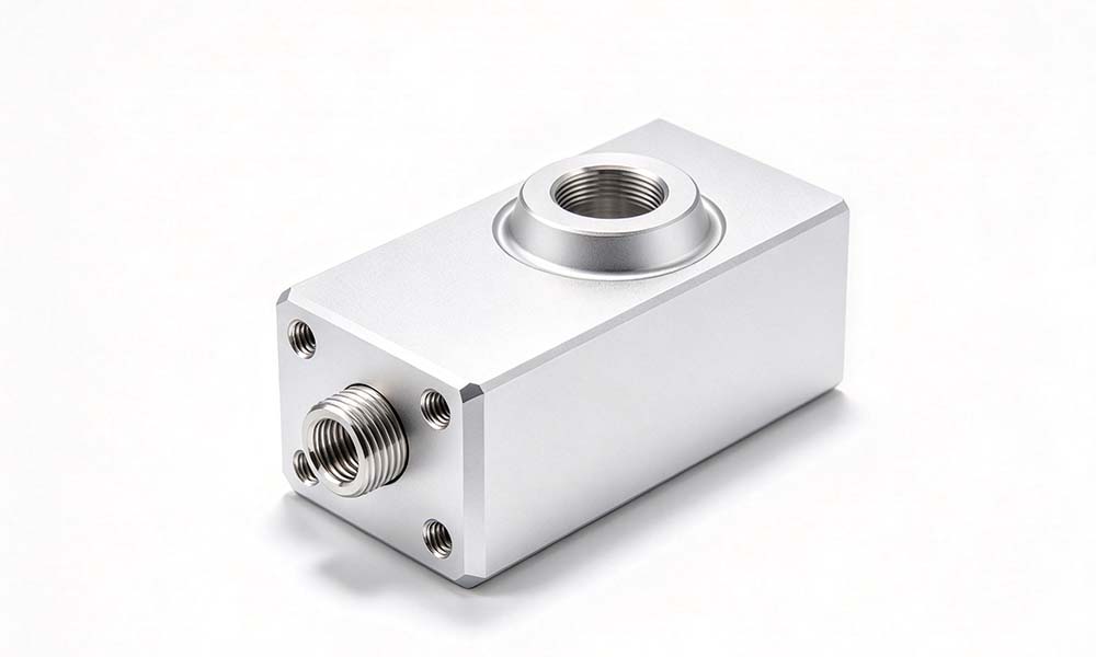
Do not publish a universal “minimum wall thickness” without the part envelope, wall height, tool diameter, unsupported length, temper, clamping and tolerance. A better DFM rule is: the thinner and taller the wall, the more aggressively the design should provide support and reduce tool engagement. Functional ribs or returns can be more valuable than a tighter tolerance callout.
Internal radii should be compatible with standard cutter diameters. A tiny internal radius forces a tiny cutter, which increases tool deflection, machining time and tool-change frequency. A larger radius often improves cycle time without changing the external function.
Separate critical assembly dimensions from non-critical dimensions. Use GD&T for location, orientation and datum relationships rather than making every linear size extremely tight. ISO 1101 provides the formal GPS framework. [14]
Leave areas that can be clamped without crushing a thin wall. If all exterior surfaces are functional, tell the supplier where temporary clamping pads or sacrificial tabs may exist. This can be removed from the part-cost problem through design rather than firefighting on the shop floor.
Specify roughness where it supports a function: sealing, sliding, optical appearance, cleanliness or friction. Do not use low Ra as a generic substitute for “looks nice.”
Design features so the required gauge or CMM stylus can actually reach them. If a hidden bore or deep pocket has a tight geometric tolerance, include adequate probe access in the design. Inspection is part of manufacturability.
Use a complete material requirement such as EN AW-5052-H32 to the specified product standard, including thickness/form and any certification requirement. Avoid “5052 aluminum” as the only contractual material description for a critical part.
Problem | Likely cause | Process factor | Corrective direction |
|---|---|---|---|
BUE + smeared finish | Adhesion at cutting edge | Too much rubbing, unsuitable geometry, dull tool, unstable chip load | Use sharper aluminum geometry; verify speed/feed together; improve chip evacuation and coolant delivery. |
Thin-wall deformation | Cutting force or clamp force exceeds local stiffness | Unsupported wall, excessive engagement, heavy final pass | Improve support, reduce engagement, rough/finish symmetrically, use lighter final passes. |
Large edge burrs | Ductile plastic deformation at exit | Tool wear, exit direction, high edge load | Change toolpath exit, replace tool, add controlled edge break and reduce unsupported edge loading. |
Batch dimensional drift | Tool wear, thermal drift or fixture variation | Long run time, uncontrolled inspection temperature | Define tool-life and in-process inspection rules; stabilize thermal conditions. |
Chip wrapping | Long ductile chips | Insufficient chip evacuation | Increase chip space/air/coolant flow; alter toolpath or drilling cycle where appropriate. |
Thermal dimensional error | Part and machine temperature change | Long cycle, hot workpiece, measurement immediately after cutting | Allow stabilization before critical inspection; control the inspection environment. |
Clamp marks / distortion | Excessive fixture pressure | Thin wall or broad flexible panel | Distribute clamping, use soft jaws/support pads, or redesign clamping zones. |
A credible B2B supplier should be able to prove process control rather than simply repeat “tight tolerance” in a sales brochure.
Supplier capability | What to verify | Why it matters |
|---|---|---|
Material traceability | Mill certificate, alloy, temper, thickness/product form, heat/lot identification | Prevents 5052/6061 swaps and temper mistakes. |
Incoming inspection | Certificate review, material marking, dimensional checks of stock | Stops wrong raw material from entering production. |
Aluminum process knowledge | Documented tool geometry, chip-control strategy, BUE troubleshooting | Shows the supplier understands 5052 as a machining material, not just a part number. |
Fixture capability | Soft jaws, support nests, vacuum or dedicated fixtures where justified | Critical for thin-wall dimensional stability. |
Inspection equipment | CMM, micrometers, height gauges, thread gauges and calibrated surface measurement as required | Inspection method needs to match drawing requirements. |
Process capability evidence | First article records, control plans, in-process checks or capability studies where appropriate | Batch consistency matters more than one good prototype. |
Engineering DFM communication | Can identify thin walls, deep pockets, unrealistic GD&T, finish risks and fixture issues before release | Moves cost and quality decisions upstream. |
Export/B2B execution | Document control, packing, labeling, inspection reporting and shipping coordination | Reduces supply-chain friction after machining is complete. |
ISO 9001 provides a quality-management-system framework for organizations that need to consistently provide conforming products and services and manage process performance. In 2026, ISO 9001:2026 has been published, replacing ISO 9001:2015, so buyers reviewing supplier certificates should check the certificate's edition/status and transition arrangements with the certification body. [18]
Production stage | Process strategy | Main control objective |
|---|---|---|
Prototype / one-off | Flexible fixturing, rapid process learning, manual deburring and targeted inspection | Validate material, geometry, datum structure and function before production fixtures are justified. |
Small batch | Standardize tools, offsets, workholding and inspection points | Reduce part-to-part variation and prevent setup-dependent dimensions. |
Medium batch | Dedicated fixture, stable tool-life rules, in-process inspection and optimized toolpaths | Lower cycle time while keeping dimensional distribution centered. |
Mass production | Production fixture, controlled raw-material lots, automated probing where practical, documented inspection plan | Control drift, yield and supply-chain repeatability. |
5052 is technically feasible for large production volumes, but production economics depend on geometry. Very thin stamped/formed parts may be more cost-effective to form than to machine from billet. Conversely, a low-to-medium volume machined housing with many functional bores may favor CNC machining because the tooling burden of a stamping or casting process is not justified.
Drawing review: confirm alloy, temper, thickness, critical features, GD&T, surface finish and inspection requirements.
DFM analysis: identify thin walls, deep pockets, tiny radii, impossible probe access and clamping risks.
Material verification: confirm EN AW-5052/AA 5052 designation, temper, product form and certificate.
Datum planning: establish a machining and inspection datum strategy that matches assembly function.
Fixture design: support flexible features without introducing damaging clamp stress.
CAM programming: separate roughing, semi-finishing and finishing logic; control engagement and tool stick-out.
Staged machining: rough, stabilize, finish and inspect in a sequence that reduces deformation risk.
In-process inspection: verify critical sizes and interfaces before a whole batch is produced from the same setup.
Final dimensional inspection: use CMM or calibrated gauges appropriate to the specified features.
Surface inspection: verify roughness/visual finish where specified; do not substitute visual judgment for measured requirements when the drawing is quantitative.
Post-processing: anodizing, brushing, polishing, marking or conversion coating as defined by the drawing.
Deburring & cleaning: remove functional burrs and chips; control contamination for assembly.
Quality report: provide material traceability, inspection results and agreed documentation.
Packaging & shipping: protect anodized/cosmetic surfaces and prevent part-to-part contact damage.
It is used for corrosion-resistant sheet/plate components, housings, panels, brackets, transportation parts and other moderate-strength applications where ductility and weldability are valuable. Exact suitability depends on temper, product form and service environment.
5052 is a non-heat-treatable Al-Mg alloy and is generally more formable and corrosion-resistant. 6061 is a heat-treatable Al-Mg-Si alloy and is widely selected for general machined structural parts where a higher strength level is useful. The right choice depends on load, environment, forming and manufacturing route.
Not in the precipitation-hardening sense used for 6061-T6 or 7075-T6. Common 5052 H tempers are obtained by cold working and stabilization. Annealing can soften the alloy, but that is not equivalent to T6 strengthening.
5052 has good corrosion resistance and is used in marine-adjacent applications, but “marine grade” is not a universal certification for every 5052 product. Where ASTM B928/B928M or another marine specification is required, the supplied product must comply with that specification. [7]
There is no single best temper. H32 is often a practical balance between strength and ductility, but the correct temper must be selected from the functional design requirement and governing material specification. Machining convenience alone should not determine temper.
It can, especially in thin walls, large flat panels and parts cut from stressed stock. The main mechanisms are elastic deflection under cutting or clamping force, residual-stress release and temperature change. Good workholding and machining sequence control reduce the risk.
The answer depends on feature size, geometry, wall thickness, temperature, machine condition, workholding and inspection method. A professional supplier should state the capability for the actual drawing feature rather than quoting one universal “5052 tolerance.”
For many milling applications, 5052 can be more prone to gummy cutting, BUE and burrs than 6061 because of its ductile material behavior. That does not make 5052 inherently unsuitable for precision CNC; it means tooling and chip-control strategy need more attention.
Yes. 5052 is listed among aluminum alloys used for anodizing. Appearance and coating response still depend on alloy lot, surface preparation and anodizing process control. [17]
It can be, but thin-wall precision is governed as much by geometry and support as by alloy. If the wall is too flexible, tightening the drawing tolerance will not solve the underlying stiffness problem.
Not inherently. Raw material, geometry, machining time, tool life, fixture complexity, inspection and finishing usually matter more than a simple alloy-to-alloy price comparison. A 5052 design can have lower total cost when its corrosion/formability advantages are actually used.
Choose based on service requirements. 5052 is often better aligned with corrosion resistance, forming, welding and moderate-load applications; 7075 is used when much higher strength is justified. The two alloys solve different engineering problems.
There is no universal requirement. The need depends on stock form, thickness, temper, machining allowance and observed movement. The supplier should evaluate residual-stress risk when large amounts of material will be removed from plate or thin stock.
At minimum, align the order with the required material certificate/traceability, drawing revision, agreed inspection report, finish requirements and packing specification. For regulated or safety-critical parts, add whatever process qualifications or special-process certificates the product specification requires.
Standards & Authoritative Sources
This page uses standards and technical references to separate normative specification requirements from typical reference data and process starting ranges. Standards are copyrighted; readers should purchase or access the complete current standard through the issuing organization for contractual or design use.
EN 573-3:2026 — Aluminium and aluminium alloys — Chemical composition and form of wrought products — Part 3: Chemical composition and form of products. Current 2026 edition; published 2026-03-18. AENOR standards page.
ANSI H35.1/H35.1M-2024 — American National Standard Alloy and Temper Designation Systems for Aluminum. The Aluminum Association.
ASTM B209/B209M-21 — Standard Specification for Aluminum and Aluminum-Alloy Sheet and Plate. ASTM International.
EN 485-2 / BS EN 485-2 — Aluminium and aluminium alloys — Sheet, strip and plate — Part 2: Mechanical properties. The BSI page identifies BS EN 485-2:2016+A1:2018 as the current released edition on that page, while European standards bodies show a 2026 replacement transition. BSI.
ASTM B928/B928M-15(2023) — Standard Specification for High Magnesium Aluminum-Alloy Products for Marine Service and Similar Environments. ASTM International.
ISO 1101:2017 — Geometrical product specifications (GPS) — Geometrical tolerancing. ISO.
ISO 2768 — Geometrical product specifications / general tolerancing. In 2026 a new edition is under publication; ISO 2768-1:1989 remains the established published reference until replaced. ISO.
ISO 21920-2:2021 — Surface texture: Profile — Part 2: Terms, definitions and surface texture parameters. ISO.
ISO 9001:2026 — Quality management systems — Requirements. ISO.
ISO 10360 series — Acceptance and reverification tests for coordinate measuring systems; relevant to metrology system qualification and CMM verification. ISO 10360-102:2026 example page.
MatWeb — Aluminum 5052-H32 / related tempers — Typical property references using Aluminum Association data and other technical references; the site explicitly warns that AA-noted values are not for design. MatWeb 5052-H32.
Aluminum Anodizers Council — Alloy Reference — Reference on alloy suitability and anodize response. AAC.
Sandvik Coromant technical guidance — BUE troubleshooting principles for cutting. Sandvik Coromant.
Harvey Tool — Aluminum-specific solid-carbide tooling families, including 3-flute and variable-helix designs. Harvey Tool.
Kennametal — Aluminum-specific milling insert geometry and grades, including BUE/burr-control design features. Kennametal.
EN AW-5052 is best understood as a corrosion-resistant, ductile, non-heat-treatable aluminum alloy whose value comes from a balanced combination of service behavior and manufacturability—not from maximum strength. Its H temper matters, its low modulus matters, and its thermal expansion matters. In CNC machining, the dominant production risks are usually not “hardness” but adhesion, chip control, burrs, flexible geometry, residual stress and thermal drift.
For B2B buyers, the most robust specification is therefore not simply “5052 aluminum.” A production-ready order should define the alloy, temper, product form, governing material standard, critical dimensions/GD&T, surface finish, post-processing, inspection requirements and traceability expectation. When these inputs are aligned with a machining process designed specifically around ductile aluminum behavior, 5052 can be a technically sound choice for corrosion-resistant housings, brackets, panels, automation parts and other moderate-load precision components.
Procurement takeaway: select 5052 because its service and manufacturing characteristics fit the part. Do not select it merely because it is common, and do not reject it merely because a supplier once experienced BUE or thin-wall deformation. Both the material choice and the machining result are process-dependent engineering decisions.
Ready to transform your CAD file into a custom part? Upload your design to get a free, precise quote.
Get Your Instant Quote