






How Should Engineers Select a CNC Machining Provider for the Humanoid Robot Industry? A Guide to 5-Axis Aluminum 6061 Machining with 0.001-Inch Tolerances
Published on Sunday, 01. November 2026
Content Guide:Engineers’ guide to choosing 5-axis CNC suppliers for Aluminum 6061 humanoid robot parts: ±0.001 in tolerance, GD&T, thin-wall control, and inspection evidence.
Select a CNC machining provider for humanoid robot parts by verifying six capabilities against the actual drawing: 5-axis process capability for the specific geometry; Aluminum 6061-T6/T651 machining and residual-stress control; GD&T and datum control; thin-wall deformation control; inspection capability including measurement uncertainty; and repeatability documentation from first article to batch. A ±0.001 in (±0.0254 mm) tolerance is a process-capability requirement, not a machine specification. It is achievable on many properly designed 6061 features, but not automatically on every feature, geometry, or production batch. If the drawing means ±0.001 mm, the requirements are substantially more demanding. The drawing governs.
Terms used in this guide: GD&T = geometric dimensioning and tolerancing; CMM = coordinate measuring machine; DFM = design for manufacturability; IMU = inertial measurement unit.
Key takeaways
5-axis CNC machining is useful for humanoid robot parts with angled surfaces, intersecting features, multiple bearing interfaces, and geometric relationships that are difficult to maintain across repeated setups.
Aluminum 6061-T6/T651 suits many robot structural and mechanical components, but final alloy selection depends on strength, stiffness, fatigue, wear, and weight requirements.
±0.001 in is a process-capability target. Tooling, workholding, temperature, material stress, machining sequence, and measurement uncertainty all affect the result.
Humanoid robot components need functional precision, not uniform tight tolerances on every dimension.
Supplier selection should be evidence-based: request comparable inspection reports, material certificates, process explanations, and repeatability records.
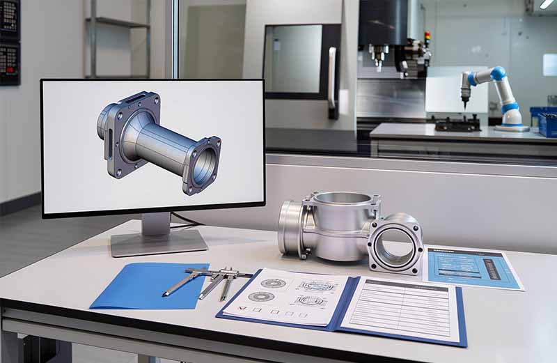
Humanoid robot joints combine motors, reduction gearboxes, bearings, shafts, actuator housings, encoders, and sensor interfaces in a compact body. The relationship between these components determines alignment, clearance, stiffness, and motion behavior. A bearing bore that is correctly sized but incorrectly positioned relative to a motor mounting interface can create assembly difficulty, unwanted mechanical loading, or joint-performance variation.
Lightweight structures add another requirement. Excess mass in arms, legs, and moving joints increases actuator load and can affect acceleration, energy use, and dynamic response. Aluminum alloys are therefore common, but the supplier must control stiffness, wall thickness, and datum relationships.
Production scale adds a third requirement: repeatability. A prototype can sometimes be hand-fitted. Production requires components that assemble consistently without extensive manual adjustment. A capable supplier should support drawing and CAD review, manufacturing feasibility analysis, repeatable workholding, controlled machining sequences, material batch identification, dimensional inspection, first-article approval, and production quality records.
Robot area | Typical CNC-machined components | Main engineering requirements |
|---|---|---|
Shoulder joint | Motor brackets, actuator housings, joint supports | Alignment, stiffness, weight |
Elbow joint | Bearing housings, connecting brackets | Bearing fit, repeatable positioning |
Wrist assembly | Compact housings, mounting plates, sensor supports | Dimensional accuracy, compact geometry |
Hip assembly | Structural supports, actuator interfaces | Load transfer, stiffness, alignment |
Knee assembly | Joint housings, mounting structures | Fatigue considerations, alignment |
Ankle assembly | Bearing supports, connecting parts | Mechanical fit, load resistance |
Robotic hand | Finger links, joint brackets, small interfaces | Compact features, repeatability |
Torso structure | Structural frames, electronics mounting plates | Flatness, rigidity, assembly accuracy |
Not every component requires the same tolerance or material. A non-load-bearing electronics bracket may not need the same precision as a gearbox housing or bearing support.
5-axis CNC machining provides three linear axes and two rotary axes. This allows the tool and workpiece to be oriented so multiple faces and angled features can be machined in a coordinated process. Typical applications include multi-directional mounting holes, angled actuator interfaces, complex joint housings, curved structural components, intersecting pockets, multiple bearing seats, and integrated mounting surfaces.
5-axis machining does not automatically guarantee higher accuracy. Its benefit depends on machine kinematics, rotary-axis calibration, workpiece positioning, fixture rigidity, CAM programming, and inspection strategy.
Method | How it works | Advantages | Limitations | Typical applications |
|---|---|---|---|---|
3-axis machining | Tool moves along X, Y, Z | Simple setup and economical for accessible features | Multiple setups may be required | Flat plates, basic brackets, simple housings |
3+2-axis machining | Two rotary axes orient the workpiece or tool; cutting uses three linear axes | Access to multiple faces in fixed orientations | Does not continuously coordinate all five axes during cutting | Angled holes, multi-face housings, mounting interfaces |
Simultaneous 5-axis machining | All five axes move in coordinated motion during cutting | Complex contours, compound angles, improved tool orientation | More demanding programming, calibration, and verification | Complex joint structures and sculpted components |
For many humanoid robot parts, 3+2-axis machining may be sufficient. Simultaneous 5-axis machining may be justified for continuously changing surface orientations or complex freeform geometry. Specify the required machining outcome rather than insisting on simultaneous five-axis motion because it sounds more advanced.
A single 5-axis setup can reduce workpiece repositioning and datum-transfer error. It does not eliminate rotary-axis errors, tool deflection, thermal effects, or fixture deformation. When evaluating a supplier, ask whether the machine supports simultaneous 5-axis machining, what the usable working dimensions and rotary-axis travel limits are, how rotary-axis accuracy is verified, how workpiece positioning is established, how datums are maintained after repositioning, whether the supplier has suitable five-axis CAM expertise, and how the resulting features are inspected. ISO 230-2 and ISO 230-3 provide useful machine-performance assessment frameworks, but neither substitutes for final component inspection.
Aluminum 6061 is a precipitation-hardenable Al-Mg-Si alloy widely used for machined structural components because it offers a practical balance of mechanical properties, machinability, corrosion resistance, and finishing options. The exact condition matters.
Condition | Description | Engineering consideration |
|---|---|---|
Solution heat-treated and artificially aged | Common where strength and machinability are required | |
Solution heat-treated, stress-relieved by stretching, and artificially aged | Relevant for plate machining where residual-stress-related distortion must be managed | |
6061-O | Annealed | Softer and more formable; not equivalent to T6/T651 mechanical properties |
For large or thin-walled aluminum components, 6061-T651 plate can be a useful starting material because stress relief by stretching helps reduce residual-stress effects. It does not eliminate distortion. Material removal can still redistribute internal stresses, especially in asymmetrical pockets, thin walls, and large stock sections. Confirm the applicable AMS/ASTM specification for the exact product form and temper on the material certificate; do not assume every 6061 product has identical properties.
Characteristic | Engineering benefit | Limitation |
|---|---|---|
Relatively low density | Supports lightweight construction | Still needs adequate structural geometry |
Useful mechanical strength | Suitable for many brackets, housings, and structural parts | Not necessarily sufficient for highly loaded components |
Good machinability | Supports complex milled and turned geometry | Thin sections can deform |
Corrosion resistance | Useful for many industrial environments | Protection may be required in aggressive environments |
Finishing compatibility | Supports anodizing and other finishes | Finishing can change dimensions |
Thermal conductivity | Helps transfer heat from selected components | Thermal behavior must be considered during machining and inspection |
7075 may be considered when strength-to-weight performance is especially important. In appropriate tempers it generally offers higher strength than 6061, but corrosion protection, finishing, welding, and cost must be considered. A stronger alloy does not automatically create a better robot component. The design must also account for fatigue, stress concentrations, contact pressure, stiffness, wear, fastening, corrosion, and manufacturing cost.
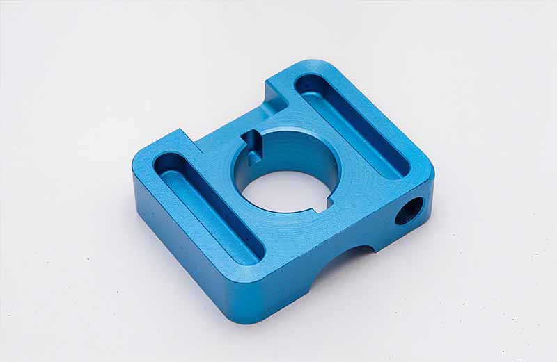
In precision CNC machining, 0.001 in = 0.0254 mm. This article assumes a requirement of ±0.001 in (±0.0254 mm) for specified dimensions. The drawing governs whether 0.001 is bilateral, total, or limit tolerance.
For a nominal bearing-bore diameter of 25.000 mm, a bilateral tolerance of ±0.0254 mm permits 24.9746 mm to 25.0254 mm. This controls the actual diameter. It does not automatically control the bore’s position, perpendicularity, coaxial relationship, or alignment with another interface.
Tolerance type | What it controls | Example robot application |
|---|---|---|
Size tolerance | Actual diameter, length, or thickness | Bearing seat diameter |
Position tolerance | Location of a feature relative to datums | Motor mounting-hole pattern |
Flatness | Surface form without reference to a datum | Joint mounting face |
Parallelism | Orientation between two surfaces or axes | Actuator mounting surfaces |
Perpendicularity | Orientation at a specified angle to a datum | Bearing bore relative to mounting face |
Profile tolerance | Overall form of a curved or complex feature | Contoured structural housing |
Runout | Variation of a rotating surface relative to a datum axis | Shaft-related interfaces |
ASME Y14.5-2018 defines GD&T principles and practices; the actual standard and drawing revision should be agreed between designer and manufacturer. Do not assign ±0.001 in to every dimension by default. Identify features that directly affect assembly, movement, alignment, or structural performance. This reduces unnecessary machining cost while protecting functional requirements.
Two suppliers can both deliver a bearing bore inside the specified diameter range and still differ in functional quality if one maintains bore position relative to the actuator mounting datum and the other does not. Procurement teams should review the complete GD&T drawing, not only the dimensional tolerance notes.
A supplier stating that its machine can achieve ±0.001 in is not sufficient evidence of production capability. Request actual inspection results from comparable components. Important variables include machine condition and positioning performance, rotary-axis calibration, tool runout and wear, workpiece stiffness, clamping deformation, cutting forces, residual material stresses, ambient and workpiece temperature, machining sequence, and inspection method.
Precision machining is a complete process system. The machine is only one part.
Machine positioning and rotary-axis calibration. Rotary-axis positioning errors, pivot-point calibration, machine geometry, and workpiece location can affect final feature position, especially when machining features at different angular orientations, intersecting holes, relationships across several faces, deep pockets, or tall components. A supplier should have documented machine verification and maintenance.
Tool selection and cutting strategy. Aluminum 6061 is generally machinable with suitable carbide tooling, but tool selection changes with geometry. Roughing removes most material; finishing establishes final dimensions and surface condition. This matters for thin-wall housings because a part may appear accurate after roughing but move during subsequent machining as material removal changes its internal stress balance.
Residual stress and thin-wall deformation. Thin-wall machining can cause local deformation under clamping, stress redistribution, wall vibration, surface waviness, and dimensional movement after unclamping. A suitable process may involve selecting appropriate stock and condition, establishing a stable datum, roughing main features, releasing the workpiece where permitted, allowing thermal stabilization, re-establishing datums when necessary, finishing critical dimensions, and inspecting in an agreed measurement condition. The exact sequence depends on geometry.
Temperature control. Aluminum expands and contracts with temperature. A dimension measured immediately after machining may differ from one measured after thermal equilibrium. The supplier should clarify inspection-room temperature, workpiece stabilization, cleaning before measurement, thermal-difference handling, calibration status, and measurement uncertainty.
Measurement capability. A part cannot be reliably accepted if the inspection system cannot confidently distinguish conforming from nonconforming dimensions. For tight tolerances, request CMM capability, probe access and measurement strategy, calibration status, measurement uncertainty, inspection repeatability, and first-piece records. A CMM is not automatically the best instrument for every feature; bore gauges, calibrated pins, precision indicators, and other instruments may be more appropriate. Machining accuracy and measurement accuracy must be evaluated together.
5-axis machining is particularly useful when a component has complex geometry or multiple precision interfaces that are difficult to manufacture through independent setups.
Actuator housings. These often combine motor mounting interfaces, bearing seats, cable passages, and structural attachment features. Requirements may include bearing-bore accuracy, mounting-hole position, concentricity or coaxial relationships where required, interface flatness, wall thickness, and thread quality.
Robotic joint structures. Shoulder, elbow, hip, knee, and ankle assemblies may use complex aluminum structural components. The process must balance structural stiffness, weight reduction, bearing and actuator alignment, fastener positioning, thin-wall rigidity, and assembly repeatability.
Robotic arm and leg links. These must provide sufficient stiffness without unnecessarily increasing moving mass. Common requirements include accurate mounting interfaces, controlled wall thickness, structural strength, repeatable holes and fastener locations, appropriate finishing, and consistent geometry across batches. Not every link needs 5-axis machining; some are more economical with 3-axis milling, turning, extrusion, or a combination.
Sensor mounts and electronics housings. These may be less structurally demanding than joint housings, but positioning can affect system integration. An IMU mounting interface may require controlled orientation relative to the robot’s reference structure. A camera or force-sensor bracket may require specific mounting geometry. The supplier should understand which surfaces are functionally important rather than applying the tightest tolerance uniformly.
Process | Advantages | Limitations | Suitable applications |
|---|---|---|---|
3-axis CNC milling | Lower process complexity for accessible geometry | More setups may be necessary | Simple mounting plates and brackets |
3+2-axis CNC machining | Efficient access to multiple faces | Limited for continuous complex contours | Multi-face housings |
Simultaneous 5-axis CNC machining | Complex geometry and coordinated tool orientation | Higher programming and machine requirements | Complex joint and actuator components |
Aluminum extrusion | Efficient for constant cross-sections | Requires additional machining for interfaces | Structural links and rails |
Aluminum die casting | Suitable for complex repeated shapes in volume | Tooling investment and post-machining requirements | High-volume housings and covers for mature designs |
Sheet metal fabrication | Economical for suitable thin structures | Limited suitability for some precision joint interfaces | Electronics covers and guards |
Metal additive manufacturing | Enables complex internal geometry | Material, surface, post-processing, and inspection considerations | Specialized lightweight designs |
5-axis machining becomes valuable when multiple precision features must be accessed at different angles or when repeated repositioning would introduce unnecessary datum-transfer risk. For a simple flat bracket, 3-axis milling may be more cost-effective. For a complex actuator housing with angled bores and multiple mounting faces, 5-axis machining may improve process efficiency and geometric consistency. The correct choice is determined by the component.
Die casting may offer lower recurring unit costs for suitable aluminum components when the design is mature and production volume is sufficiently high. It requires tooling investment and often still needs CNC machining for precision interfaces. A mixed process can be appropriate: die-cast the general housing, CNC-machine bearing seats and assembly surfaces, finish, and inspect critical dimensions. For prototypes and early design iterations, CNC machining may be preferable because design changes do not necessarily require new casting tools.
A supplier should have a clear quality-control workflow from incoming material to finished component inspection.
Incoming material inspection. Confirm alloy designation, temper condition, material form, supplier documentation, material identification, stock dimensions, and surface condition. For critical components, material certificates should be linked to the supplied stock and, where required, to finished-part production records.
First-article inspection. FAI checks whether the manufacturing process can produce the specified geometry. A suitable FAI report should cover overall dimensions; critical interfaces such as bearing seats, mounting faces, and mating surfaces; hole diameter, position, depth, and thread specification; geometric relationships such as position, perpendicularity, parallelism, and flatness; surface finish and visible defects; alloy, temper, and material documentation; and finishing effects where applicable.
In-process inspection. Check dimensions after roughing, measure critical features after finishing, verify tool condition, check workpiece positioning, and monitor recurring dimensional trends. This is especially valuable where distortion may develop after successive operations.
Final inspection and documentation. Possible documentation includes dimensional inspection reports, material certificates, FAI reports, CMM records, nonconformance documentation, finishing records, and production lot identification. The customer and supplier should agree on inspection scope before production.
ISO 9001 certification can help buyers evaluate a quality-management system, but it does not prove that every machine or part meets the drawing. Check the certificate’s issuing body, validity, scope, and covered manufacturing location. Do not assume an ISO certificate guarantees ±0.001-inch machining performance.
Cost depends on more than finished dimensions. A complex joint housing may require significant programming, material removal, specialized fixturing, finishing, and inspection even if the final component is relatively small. The important procurement question is the total cost of obtaining consistently conforming components.
Cost factor | Effect on manufacturing cost | Procurement strategy |
|---|---|---|
Aluminum 6061 material | Grade, temper, stock size, and wastage affect cost | Specify the exact alloy and condition |
5-axis programming | Complex toolpaths and setup planning require engineering time | Provide complete CAD models and drawings |
Machining time | Deep pockets, complex contours, and material removal affect cycle time | Review geometry with the supplier |
Tight tolerances | Require controlled processes and additional verification | Apply tight tolerances only to functional features |
Thin-wall machining | Requires careful support, sequencing, and finishing | Review wall thickness and geometry early |
Tooling | Specialized cutters and replacement frequency affect cost | Ask about tool-life management |
Workholding | Complex components may require dedicated fixtures | Consider fixture costs across order quantity |
Surface finishing | Anodizing or other treatments add processing cost | Specify finish and dimensional requirements |
Inspection | CMM, dimensional checks, and reporting require resources | Define the required inspection level |
Production volume | Setup, programming, and fixture costs are distributed across the batch | Compare prototype and production quotations |
Tight tolerances increase cost because they require additional machining operations, more accurate workholding, controlled roughing and finishing, additional measurement, more detailed process documentation, and higher inspection levels. A joint housing with ten ±0.001-inch dimensions may cost substantially more than one where only two bearing interfaces carry that tolerance. Drawing optimization can produce meaningful savings.
Do not compare prices until quotations cover the same technical requirements. A useful comparison should include material grade and temper, 5-axis machining strategy, critical tolerance confirmation, GD&T capability, material certification, FAI, CMM or alternative inspection method, surface finishing, prototype price, batch price, production lead time, packaging, and traceability. A low quotation that excludes finishing, inspection, or material traceability may ultimately become more expensive.
DFM is important because humanoid robot parts often contain compact interfaces, lightweight structures, and complex mounting geometry. A supplier should review the design before production.
Optimize wall thickness. Thin walls reduce weight but create machining challenges: deformation during clamping, vibration during milling, stress-related movement after material removal, difficulty maintaining flatness, and increased sensitivity to tool engagement. Avoid unnecessary variations in wall thickness and discuss fixture design and machining sequence where thin structures are necessary.
Consider internal corner radii. CNC milling tools have physical diameters, so internal corners cannot generally be manufactured as perfectly sharp corners using conventional rotary cutting tools. Extremely small internal radii may require smaller cutting tools, additional machining time, greater tool deflection, and more complicated toolpaths. Where functional requirements permit, suitable internal radii improve manufacturability.
Design bearing interfaces carefully. Clearly identify bearing type and fit requirements, bore diameter and tolerance, bore-axis relationships, reference datums, shoulder geometry, surface-finish requirements, and assembly conditions. Select fits according to the bearing manufacturer’s specifications and actual operating conditions. Do not assume every bearing requires the same interference or clearance fit.
Account for anodizing and surface treatment. Anodizing may affect dimensions. Specify the type of anodizing, required coating thickness or applicable standard, whether dimensions are before or after finishing, which surfaces must remain uncoated, whether electrical contact or grounding surfaces are needed, and any cosmetic requirements. Discuss dimensional allowances and masking for precision bores and bearing seats before machining.
Avoid unnecessary complex 5-axis features. Use 5-axis machining because the geometry requires it, not because every surface is made more complex. A flat bracket with simple mounting holes may be cheaper to produce using conventional 3-axis machining. Overcomplicated geometry increases programming, machining, inspection, and procurement costs without necessarily improving robot performance.
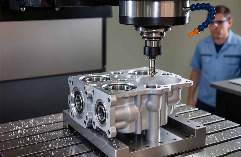
Machining problem | Possible root cause | Potential consequence | Recommended response |
|---|---|---|---|
Thin-wall deformation | Clamping pressure or machining force | Dimensional deviation | Improve workholding and machining sequence |
Bearing-bore deviation | Tool deflection, thermal variation, or setup error | Poor bearing fit | Review boring strategy, datums, and inspection |
Hole-position errors | Incorrect workpiece orientation or datum transfer | Assembly interference | Improve probing and coordinate setup |
Poor surface finish | Tool wear, vibration, or incorrect cutting conditions | Surface-quality problems | Review tooling and cutting strategy |
Dimensional changes after unclamping | Residual-stress redistribution or clamping deformation | Parts fail final inspection | Introduce staged machining and relaxed-state inspection |
Rotary-axis-related errors | Calibration or kinematic compensation problems | Angular-feature deviation | Verify rotary-axis performance |
Tool collision | Inadequate CAM simulation or setup planning | Scrap and equipment damage | Improve collision checks and process verification |
Anodizing-related dimensional deviation | Coating allowance not considered | Incorrect final fit | Establish pre- and post-finish dimensions |
Thread defects | Incorrect tool selection or machining strategy | Assembly and fastening problems | Verify thread standards and inspect threads |
Inconsistent batch dimensions | Tool wear, thermal changes, or process variation | Increased rejection rate | Establish process monitoring and inspection controls |
If a bearing bore measures within tolerance during machining but falls outside tolerance after unclamping, a superficial response is to change the cutting tool. A more effective investigation examines whether the fixture deformed the component, whether the bore was machined before or after significant material removal, whether residual-stress-related movement occurred, whether workpiece temperature differed between machining and inspection, whether the measurement setup was repeatable, and whether the datum system was properly established. The supplier should document the root cause and verify corrective action with repeat inspection.
A supplier may advertise five-axis capability and high precision but still lack the process controls needed for humanoid robot components. Assess the provider in six areas.
5-axis equipment and process capability. Ask how many axes the required machine coordinates during cutting, whether it can manufacture the actual part geometry, what the usable machining dimensions are, how rotary axes are calibrated, how datums are maintained across multiple faces, whether the supplier has appropriate five-axis CAM expertise, and whether it can provide evidence of machining comparable components.
Aluminum material experience. The supplier should understand 6061-T6, 6061-T651, and other requested conditions. Ask whether it can source the specified temper, provide material documentation, control residual-stress-related deformation, approach thin-wall machining, and protect finished parts during transportation.
Precision and GD&T expertise. The supplier should interpret the drawing, identify critical dimensions, and explain the proposed inspection method. It should understand datum reference frames, position tolerances, flatness and perpendicularity, bearing fits, bore-axis relationships, surface-finish requirements, and pre- and post-finishing dimensions.
Quality-control capabilities. Request FAI reports, CMM inspection results, material certificates, dimensional inspection documentation, process-control records, and nonconformance/corrective-action procedures. For repeat production, ask how dimensional variation is monitored across batches.
Engineering communication and DFM support. A good partner identifies production risks before machining: inaccessible bearing bores, thin walls that may deform under clamping, internal corners requiring impractically small tools, coating allowances that interfere with fits, or tolerances that are unnecessarily restrictive. The supplier should explain engineering consequences and offer practical alternatives.
Production capacity and supply-chain reliability. Review available machining resources, production planning, material availability, subcontracted processes, inspection capacity, delivery planning, packaging, export arrangements, and communication during production changes.
Evaluation category | Suggested weighting | What to verify |
|---|---|---|
5-axis CNC capability | 20% | Relevant machines, kinematics, CAM capability |
Precision machining | 20% | Actual ±0.001-inch feature inspection evidence |
Aluminum 6061 expertise | 15% | Material sourcing, machining, deformation control |
Quality inspection | 15% | CMM, calibrated instruments, inspection reports |
DFM and engineering support | 10% | Drawing review and engineering recommendations |
Production repeatability | 10% | FAI approval and process controls |
Delivery and communication | 10% | Production planning and communication procedures |
These are suggested procurement weightings, not an industry standard. Adjust them according to whether the component is safety-critical, structurally important, or primarily a prototype. Never award a precision robotics project solely because a supplier has the lowest price or the largest advertised machine inventory.
Production stage | Main objective | CNC machining priorities | Inspection priorities |
|---|---|---|---|
Initial prototype | Confirm geometry and assembly | Design flexibility and DFM | Critical dimensions and fit |
Functional prototype | Validate mechanical operation | Repeatable machining of interfaces | Bore position, alignment, assembly |
Engineering validation | Evaluate design under intended conditions | Stable materials and process | Dimensional and material documentation |
Pilot production | Establish production feasibility | Fixtures, process planning, repeatability | FAI and batch verification |
Batch production | Maintain consistent manufacturing | Tool management and process control | Agreed production inspection plan |
A prototype that works is not necessarily production-ready. Some components may require revised wall thickness, improved tool access, different datum features, modified tolerances, improved fastening geometry, or revised finishing requirements. A supplier involved early can identify these issues before the design becomes expensive to change.
For repeat orders, ask the supplier to maintain approved drawing revisions, material specifications, approved FAI records, production setup documentation, inspection criteria, tool replacement procedures, lot identification, and change-control records.
1. How should engineers choose a CNC machining supplier for humanoid robots?
Choose based on 5-axis capability, relevant aluminum machining experience, GD&T knowledge, inspection capability, and production repeatability. Request comparable inspection reports, material documentation, and examples of similar components.
2. Can 5-axis CNC machining achieve ±0.001-inch tolerances?
Yes, many appropriately designed aluminum features can be manufactured to ±0.001 in. Capability depends on geometry, machine condition, workholding, tool selection, thermal stability, material condition, and inspection method. The supplier should confirm feasibility against the actual drawing.
3. Is 0.001 inch the same as 0.001 mm?
No. 0.001 in equals 0.0254 mm. 0.001 mm equals approximately 0.0000394 in. The latter is an extremely demanding tolerance and should not be assumed achievable through ordinary precision CNC machining. Always specify the unit, tolerance zone, and acceptance requirements.
4. Why is 5-axis CNC machining used for humanoid robot joint housings?
It provides access to multiple faces and angled features while potentially reducing workpiece repositioning. This can help maintain relationships between bearing bores, motor interfaces, and mounting features. It does not automatically guarantee better precision.
5. Is Aluminum 6061-T6 suitable for humanoid robot components?
Yes, for many structural brackets, housings, actuator supports, and mechanical components. Final alloy selection should be based on strength, stiffness, fatigue performance, loading conditions, and weight targets.
6. Should engineers choose 6061-T6 or 6061-T651?
The choice depends on material form and application. 6061-T651 is particularly relevant to stress-relieved plate. For large machined plates or parts with substantial material removal, T651 may be advantageous, although it does not eliminate machining distortion.
7. Is 6061 better than 7075 for humanoid robot structures?
Not universally. 6061 offers a useful balance of strength, machinability, corrosion resistance, and cost. 7075 may be preferable where higher strength-to-weight performance is required, provided corrosion, finishing, and manufacturing considerations are acceptable.
8. What documents should buyers request from a CNC machining supplier?
Depending on the project: material certificates, approved engineering drawings, FAI reports, dimensional inspection reports, relevant CMM records, finishing documentation, production lot identification, and quality-system documentation.
Selecting a CNC machining provider for humanoid robot components requires understanding material condition, machining strategy, geometric tolerances, quality control, and production repeatability. 5-axis CNC machining offers important advantages for complex actuator housings, joint structures, bearing interfaces, and multi-face aluminum components. Aluminum 6061 provides a practical material option for many lightweight mechanical structures, but temper selection and deformation control remain essential.
A tolerance of ±0.001 in should be evaluated against the actual drawing, machine capability, fixture strategy, and inspection evidence. The most suitable partner is not necessarily the supplier with the most machines or the lowest quotation. It is the manufacturer that can understand the engineering function of each component, establish a suitable manufacturing process, verify critical dimensions, and maintain consistent quality from prototype to production.
Standards referenced: ASME Y14.5-2018; ISO 230-2; ISO 230-3; ISO 9001.
Previous:Can FR4 Be CNC Machined? How to Prevent Delamination and Fiber Burrs
Next:No More/End
Ready to transform your CAD file into a custom part? Upload your design to get a free, precise quote.
Get Your Instant Quote