




What Is 5-Axis CNC Machining in 2026? A Complete Guide to Process, Accuracy, Cost, Applications, and Design
Published on Wednesday, 09. September 2026
Content Guide:Learn what 5-axis CNC machining is, how it works, 3+2 vs simultaneous 5-axis, accuracy, materials, cost factors, DFM guidelines, applications, and how to choose a supplier.
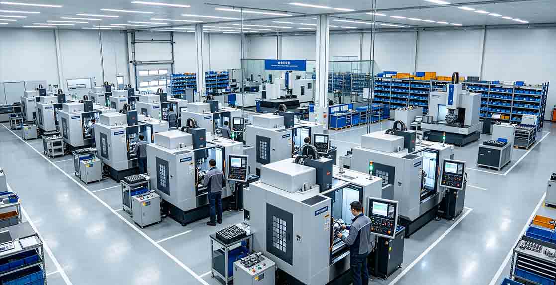
5-axis CNC machining is a subtractive manufacturing process that uses three linear axes and two rotary axes to position and move a cutting tool relative to a workpiece. Unlike conventional 3-axis machining, a 5-axis machine can change the tool orientation as well as the tool position, allowing the cutting tool to approach complex surfaces from different directions.
That definition is technically correct, but it misses the most important manufacturing point.
The real advantage of 5-axis CNC machining is not simply having “two more axes.” Its value comes from giving the manufacturing engineer more control over tool access, tool orientation, setup strategy, and the relationship between multiple machined surfaces.
For a complex aerospace component, impeller, robotic joint, medical component, deep cavity, or contoured housing, the difference can be substantial. A feature that requires several setups on a 3-axis machine may be machined in fewer setups on a 5-axis machine. Fewer setups can simplify fixturing and reduce opportunities for setup-related variation.
But that does not mean 5-axis machining is automatically more accurate, faster, or cheaper.
A simple prismatic aluminum block with accessible pockets may be more economical on a 3-axis machining center. A rotational part may be better suited to CNC turning or mill-turn machining. A high-volume component may justify dedicated tooling and a simpler cycle even when a 5-axis machine is capable of producing it.
So the correct question is not:
“Is 5-axis CNC better than 3-axis CNC?”
The better question is:
“Does the geometry, tolerance structure, surface requirement, and production volume justify the additional kinematic capability of a 5-axis process?”
That engineering distinction is the foundation of this guide.
5-axis CNC machining combines:
· Three linear axes: X, Y, and Z
· Two rotary axes selected from A, B, and C
· CNC control and machine kinematics
· CAM-generated toolpaths
· A workholding strategy designed around the available machining directions
The three linear axes describe movement along straight Cartesian directions. The rotary axes rotate either the workpiece, the cutting tool, or the machine head/table assembly, depending on the machine architecture.
The exact mechanical arrangement differs between machine designs, but the manufacturing objective is the same: create additional degrees of freedom for positioning the cutting tool relative to the workpiece.
A 5-axis machine normally does not use X, Y, Z, A, B, and C all at once. It uses three linear axes plus two rotary axes.
Like other CNC milling processes, 5-axis machining removes material from a solid workpiece using a rotating cutting tool.
The difference is that the cutting tool can approach the part from more directions.
On a typical 3-axis machine, the cutting tool moves primarily in X, Y, and Z. If a feature is hidden behind another surface or positioned at an unfavorable angle, the part may have to be physically rotated and re-fixtured.
With 5-axis machining, the machine can rotate the tool or part to improve access without necessarily removing the workpiece from the fixture.
That additional access can affect:
· the number of setups,
· cutter reach,
· tool orientation,
· fixture design,
· machining time,
· surface quality,
· positional relationships between features,
· and inspection strategy.
This is why the engineering value of 5-axis CNC machining is better understood as process flexibility rather than simply “more axes.”
A professional 5-axis CNC machining process typically follows this chain:
CAD model → CAM programming → toolpath generation → machine coordinate transformation → workholding → cutting → inspection
Each stage matters.
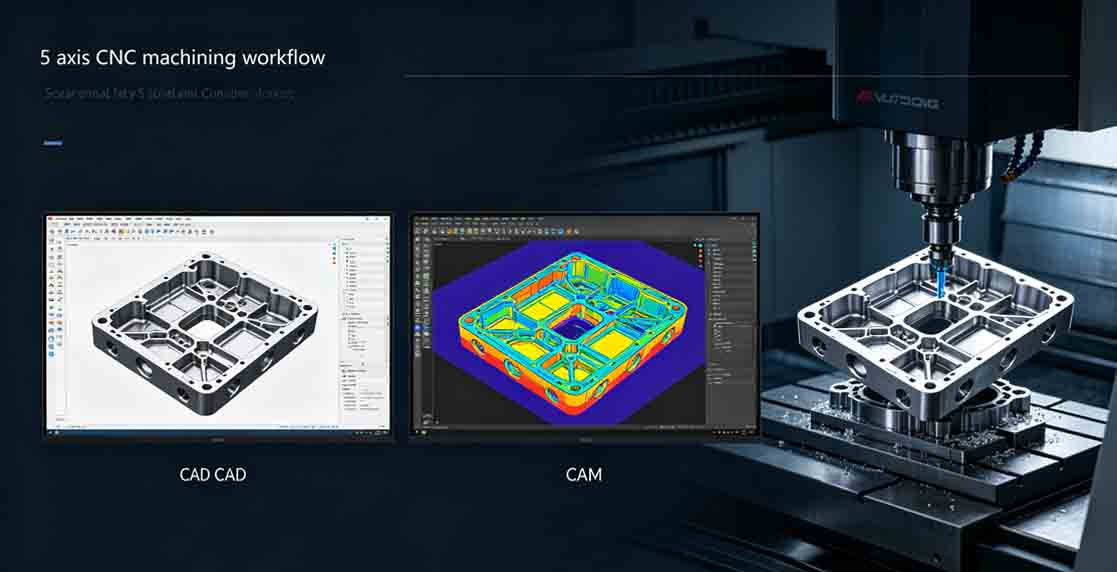
The process begins with a 3D CAD model and manufacturing drawing.
The engineer must understand not only the final geometry but also:
· critical dimensions,
· datums,
· geometric tolerances,
· surface finish requirements,
· material,
· threads,
· holes,
· thin walls,
· deep cavities,
· and functional surfaces.
A 5-axis machine does not eliminate design-for-manufacturing constraints. In fact, complicated geometry can make design interpretation even more important because tool orientation changes throughout the machining process.
The CAM engineer converts the CAD geometry into machining strategies and toolpaths.
For relatively simple features, the process may still look similar to conventional 3-axis milling.
For freeform surfaces, however, CAM programming may control:
· tool axis orientation,
· lead and lean angles,
· tool engagement,
· collision avoidance,
· cutting direction,
· step-over,
· scallop height,
· and transitions between surfaces.
The quality of the final component therefore depends partly on the relationship between the CAM system and the physical machine.
The CAM system generates tool motion based on the desired cutter location and orientation.
The key concept is that the tool does not only have a position.
It also has an orientation.
That orientation influences how the cutter contacts the part.
For example, changing the tool angle can:
· improve access to a surface,
· shorten effective tool reach,
· reduce the risk of rubbing,
· improve cutting conditions,
· or produce a more consistent surface finish.
The correct orientation is not necessarily the most aggressive orientation. It is usually the one that provides an acceptable balance between accessibility, tool engagement, rigidity, surface quality, and collision clearance.
The CAM system must translate the desired tool orientation into actual movement of the machine's linear and rotary axes.
This is a kinematics problem.
The machine controller must understand how movements of the rotary axes affect the tool center point relative to the workpiece.
This becomes particularly important during simultaneous 5-axis machining, where several axes may move together.
A sophisticated machine cannot compensate for poor fixturing.
Workholding must provide:
· adequate rigidity,
· repeatable location,
· sufficient clearance,
· stable support,
· and access to the required surfaces.
One of the major advantages of 5-axis machining is that the part may require fewer physical repositioning operations.
But this only helps when the fixture is designed correctly.
During machining, spindle speed, feed rate, depth of cut, tool geometry, coolant strategy, tool engagement, and machine rigidity all interact.
The machine's five-axis capability expands the available machining strategies, but it does not override cutting mechanics.
· A long tool will still deflect.
· A weak fixture will still vibrate.
· An unstable setup will still produce poor surface finish.
· A poorly selected toolpath can still damage a part.
Inspection closes the manufacturing loop.
Depending on the part, inspection may involve:
· calipers and micrometers,
· height gauges,
· gauges,
· optical measurement,
· probing,
· or coordinate measuring machines.
For complex multi-surface components, inspection planning should be considered before machining rather than added at the end.
Axis | Typical Meaning | Movement |
X | Linear axis | Left/right |
Y | Linear axis | Front/back |
Z | Linear axis | Up/down |
A | Rotary axis | Rotation around X |
B | Rotary axis | Rotation around Y |
C | Rotary axis | Rotation around Z |
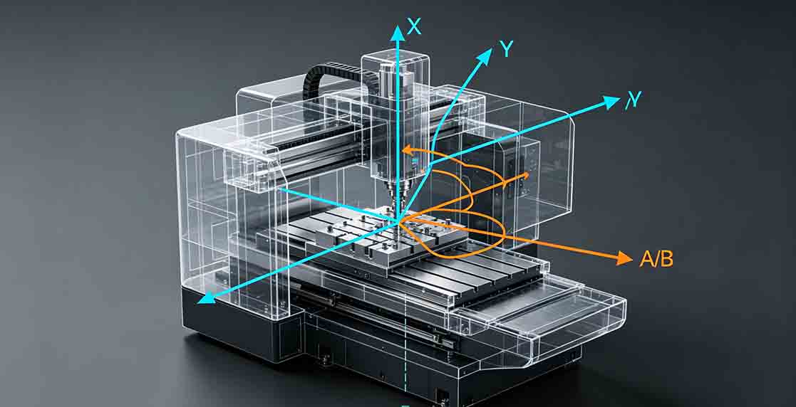
A machine's five axes are normally:
X + Y + Z + two rotary axes
The two rotary axes can be combinations such as:
A + B
A + C
B + C
The actual machine architecture depends on whether the rotary motion is provided by a rotary table, tilting table, swivel head, or a combination of mechanisms.
This distinction matters to buyers.
Two machines can both be described commercially as “5-axis CNC machines” while having very different:
· work envelopes,
· spindle configurations,
· rotary-axis capacities,
· workholding limitations,
· accessibility,
· and practical production behavior.
For complex work, the machine configuration matters almost as much as the number “5.”
Not every 5-axis job requires continuous five-axis movement.
There are two important machining approaches:
Factor | 3+2 Machining | Simultaneous 5-Axis |
Axis movement | Rotary axes position the tool, then cutting is usually 3-axis | Multiple axes can move simultaneously during cutting |
Tool orientation | Fixed during an indexed operation | Continuously changing during machining |
Programming complexity | Lower | Higher |
Surface access | Very good for angled faces | Excellent for complex/freeform surfaces |
Typical applications | Multi-sided prismatic parts | Impellers, blades, sculpted surfaces, complex geometry |
Setup strategy | Reduces physical setups while indexing | Can minimize repositioning and enable continuous tool orientation |
Cost implications | Often simpler to program and validate | Potentially higher programming and verification effort |
Geometric complexity | Moderate to complex | Complex to highly complex |
A 3+2 process uses the two rotary axes primarily to orient the part or tool.
The machine positions the rotary axes at a specific angle, then performs a conventional 3-axis cutting operation.
After that operation, the machine indexes to another angle.
This is extremely useful for components with multiple angled surfaces.
It provides many of the practical advantages of five-axis equipment without requiring fully simultaneous five-axis motion throughout the cut.
In simultaneous 5-axis machining, the machine can coordinate linear and rotary axes during the cut.
The tool orientation can change continuously as the cutter travels across a surface.
This is especially valuable for:
· impellers,
· blades,
· turbine components,
· deep curved surfaces,
· complex molds,
· medical geometry,
· and highly contoured freeform components.
But simultaneous machining also introduces greater programming complexity, more opportunities for collision, and greater dependence on machine kinematics and CAM post-processing.
Therefore:
A 5-axis machine does not mean every operation should be programmed as simultaneous 5-axis machining.
An experienced manufacturer chooses the simplest process capable of reliably meeting the drawing requirements.
Why Use 5-Axis CNC Machining?
The practical advantages of 5-axis CNC machining usually come from six areas.
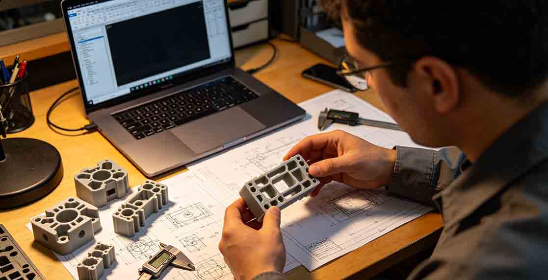
Consider a component with important features on five different sides.
On a 3-axis machine, the component may need to be repositioned several times.
Every repositioning creates another opportunity for:
· datum variation,
· fixture variation,
· alignment error,
· setup time,
· and operator intervention.
A 5-axis process may allow several surfaces to be accessed from one primary setup.
This does not guarantee perfection, but it can simplify the process chain.
Deep pockets and angled surfaces can force a 3-axis machine to use long tools.
Long tools are less rigid and more sensitive to:
· deflection,
· vibration,
· chatter,
· and poor surface finish.
A 5-axis machine can sometimes tilt the tool into a better cutting direction, allowing the use of a shorter, more rigid cutter.
Tool orientation is one of the most important reasons for using simultaneous 5-axis machining.
A cutter does not perform identically at every orientation.
Changing its angle can influence:
· engagement,
· effective cutting diameter,
· chip evacuation,
· tool deflection,
· surface generation,
· and local accessibility.
For freeform surfaces, tool orientation becomes part of the machining strategy rather than simply a positioning function.
If a component can be machined from more directions without being removed from its fixture, some physical repositioning operations can be eliminated.
That can reduce process-chain length.
Fewer setups can reduce the number of dedicated fixtures needed.
However, this is not always true.
A complex 5-axis fixture can be more expensive than a simple 3-axis fixture.
The correct comparison is the total manufacturing system, not the fixture in isolation.
For contoured surfaces, continuously changing tool orientation can produce better access and help maintain more favorable cutter engagement.
This is one reason 5-axis machining is widely associated with aerospace structures, blades, impellers, molds, and other freeform geometries.
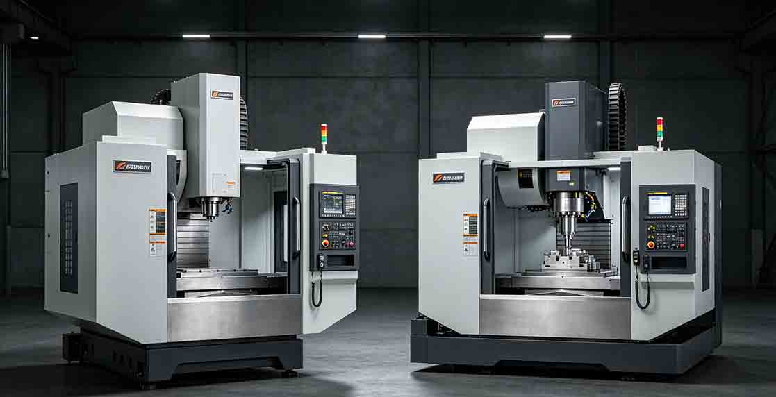
Not automatically.
This is one of the most important distinctions a buyer should understand.
A five-axis machine does not magically produce smaller tolerances simply because it has more axes.
Manufacturing accuracy depends on the complete process.
Important variables include:
· machine accuracy,
· repeatability,
· rotary-axis performance,
· spindle condition,
· thermal stability,
· fixture rigidity,
· workholding location,
· tool deflection,
· cutting forces,
· CAM calculations,
· post-processor behavior,
· material behavior,
· and inspection methodology.
A useful engineering principle is:
5-axis machining can improve the consistency of a multi-surface process, but five-axis capability itself is not a substitute for machine accuracy or process control.
Suppose two holes must maintain a tight positional relationship.
On a multi-setup process, the relationship depends partly on how consistently the workpiece is relocated between operations.
Reducing physical repositioning can remove one source of process variation.
That is a genuine advantage.
Rotary axes introduce their own potential error sources.
ISO 230-2:2014 provides test methods for evaluating positioning accuracy and repeatability of numerically controlled machine-tool axes, and these methods apply to both linear and rotary axes. The standard remains current following its most recent review in 2025.
This is why a serious supplier should not answer an accuracy question using only a statement such as:
“Our 5-axis machine is very accurate.”
A better engineering discussion considers:
· what tolerance is required,
· on which features,
· under what datum scheme,
· on what material,
· over what feature size,
· with what inspection method,
· and under what production conditions.
There is no single universal tolerance that can honestly be applied to every 5-axis part. The achievable result depends on the process system.
· Machine Condition: A well-maintained machine behaves differently from one with worn bearings, spindle problems, backlash, or poorly controlled rotary-axis behavior.
· Rotary Axis Accuracy: Rotary-axis positioning affects the orientation and location of features. This becomes especially important when multiple surfaces must maintain strict geometric relationships.
· Workholding: A rigid, repeatable fixture is essential. A highly accurate machine can still produce poor results if the component moves during cutting.
· Cutting Strategy: The cutting process produces forces. Those forces interact with tool stiffness, holder rigidity, workpiece geometry, fixture stiffness, and machine structure.
· Tool Selection: Tool diameter, length, geometry, coating, material, and holder design all influence cutting behavior.
· Thermal Behavior: Temperature can influence machine geometry, material dimensions, and process stability. ISO 230-2 specifically identifies environmental and thermal considerations as relevant to machine performance and positioning testing.
· Material: Aluminum, stainless steel, titanium, hardened tool steel, copper, and engineering plastics behave differently during machining. The same process settings cannot simply be transferred from one material to another.
· Part Geometry: A thin wall is fundamentally different from a rigid block. A long unsupported surface is fundamentally different from a short, thick feature. Geometry influences the achievable result as much as nominal machine capability.
· Inspection System: A tolerance only has meaning when it can be properly measured. For critical features, the inspection method should be selected according to feature geometry, tolerance, measurement uncertainty, accessibility, and functional importance.
5-axis machining can improve surface generation on certain complex geometries, but surface finish still depends heavily on process control.
· Tool Orientation: Tilting the tool can change the cutter-to-surface relationship. For some surfaces, this can avoid unfavorable contact conditions and produce a more controlled finish.
· Toolpath Strategy: Poor toolpath transitions can leave visible marks even when the machine itself is capable of high-quality motion.
· Scallop Height: On freeform surfaces, toolpath spacing influences the remaining scallop between adjacent passes. Smaller scallops generally require closer toolpath spacing, which may increase machining time.
· Cutter Diameter: Cutter size affects accessibility, curvature compatibility, and surface generation.
· Finishing Passes: A roughing strategy optimized for material removal is not necessarily suitable for the final surface. A separate finishing strategy is often needed.
· Tool Rigidity: Tool length and diameter strongly influence deflection. A short, rigid cutter is usually easier to control than a long, slender cutter.
· Spindle Condition: Runout and spindle condition influence surface quality, tool life, and dimensional stability.
· Material Behavior: Aerospace aluminum, stainless steel, titanium, and engineering plastics have different cutting characteristics.
The correct five-axis strategy therefore begins with the material, geometry, and functional surface requirements—not with the machine name.
5-axis machining is compatible with a wide range of metals and engineering plastics. The practical challenge is selecting cutting strategies and workholding systems appropriate to each material.
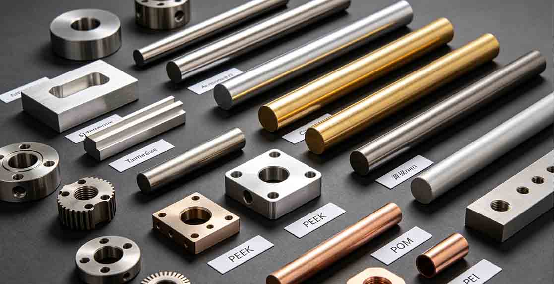
Machinability: Generally favorable.
Heat generation: Relatively manageable compared with difficult-to-machine alloys, although heat can still become important in deep cavities and high-speed operations.
Tool considerations: Sharp cutting edges and suitable flute geometry are important, particularly for chip evacuation.
Rigidity considerations: Thin aluminum walls can deform under cutting forces.
Common applications: Aerospace structures, housings, robotic components, automotive parts, fixtures, and precision prototypes.
5-axis machining is particularly useful when an aluminum component contains multiple angled surfaces or requires reduced setup count.
Machinability: More demanding than many aluminum grades.
Heat generation: Can be significant because stainless steels generally conduct heat less readily than aluminum.
Tool considerations: Tool selection, cutting parameters, coolant, and chip control become important.
Rigidity considerations: Stable workholding and adequate tool rigidity help reduce chatter.
Common applications: Industrial equipment, medical components, food-processing equipment, automotive systems, and mechanical assemblies.
Carbon steels cover a broad range of machinability.
The correct cutting strategy depends on the specific grade and condition.
Applications include: structural components, machinery parts, brackets, shafts, tooling components, and industrial assemblies.
Tool steels can range from relatively machinable annealed material to difficult hardened material.
The material condition is therefore critical.
5-axis capability becomes useful when hard tooling components contain complex surfaces, angled cavities, or difficult access requirements.
Titanium is a strong candidate for advanced machining strategies because cutting conditions can be demanding.
Important concerns include: heat concentration, tool wear, cutting force, rigidity, and toolpath stability.
5-axis machining can help by improving cutter orientation and reducing unnecessary tool reach.
Typical applications include: aerospace components, medical parts, robotic structures, and high-performance mechanical components.
Brass is generally machinable, although different alloys have different cutting behavior.
Typical applications include: fittings, precision components, electrical hardware, and decorative/mechanical parts.
Copper presents different challenges from steel or aluminum because of its material behavior and tendency to create machining issues under unsuitable conditions.
Stable fixturing, suitable tooling, and careful process control are important for complex copper parts.
Nickel-based alloys such as Inconel are significantly more demanding to machine than common aluminum alloys.
Cutting-tool selection, thermal management, rigidity, and toolpath strategy become particularly important.
5-axis capability may help access difficult surfaces, but it does not make Inconel easy to machine.
PEEK can be machined with CNC equipment, including 5-axis machines.
Because plastics respond differently to heat and mechanical loading than metals, the process must account for: heat generation, dimensional behavior, workholding, burr formation, and material support.
Common applications include medical, electrical, chemical, and specialized industrial components.
POM is generally considered a highly machinable engineering plastic.
It is commonly used for: gears, bushings, rollers, guides, mechanical housings, and low-friction components.
The main challenge is often controlling dimensional stability and avoiding deformation of thin features.
Nylon can be CNC machined but is more compliant than metals.
Part support and environmental considerations can influence dimensions and repeatability.
Typical applications include: bushings, guides, housings, mechanical prototypes, and lightweight components.
PEI is a high-performance engineering thermoplastic used where thermal and mechanical performance exceeds conventional commodity plastics.
Machining requires attention to: heat, tool geometry, workholding, edge quality, and dimensional stability.
The best candidates for 5-axis machining are not defined by industry alone.
They are defined by geometry and access requirements.
· Aerospace Components: Aerospace components often contain curved surfaces, lightweight structures, multiple angled faces, pockets, and closely related features. 5-axis machining can reduce repositioning and improve tool access.
· Robotic Parts: Robotic joints, housings, arms, brackets, and end-effector components often combine several mounting surfaces and intersecting features. The ability to control multiple surfaces from a common datum structure can be valuable.
· Automotive Parts: Automotive applications may include housings, brackets, tooling components, prototype components, structural parts, and performance components. However, high-volume automotive manufacturing should not automatically default to 5-axis machining. The best process depends on volume and cycle economics.
· Medical Components: Complex medical components can contain small features, curved geometry, and difficult access areas. Material selection and inspection requirements become particularly important.
· Energy Components: Energy equipment can involve large components, complex channels, manifolds, and difficult internal or angled surfaces. The machine envelope becomes especially important for these applications.
· Impellers: Impellers are classic five-axis applications. Their blades contain continuously varying geometry that is difficult to machine efficiently using only simple fixed orientations.
· Complex Housings: A housing may contain external faces, angled ports, deep pockets, internal cavities, mounting holes, and multiple datum surfaces. Reducing the number of setups can simplify manufacturing.
· Manifolds: Manifolds often contain intersecting channels and holes at different orientations. 5-axis positioning can improve accessibility and fixture efficiency.
· Structural Components: Large lightweight structures may combine thin walls, pockets, rib structures, angled surfaces, and multiple datums. The value of 5-axis machining depends strongly on rigidity and workholding.
· Prototypes and Production Parts: 5-axis machining can be useful for both prototypes and production. But the process strategy should change with quantity. A prototype might prioritize flexibility and speed of engineering changes. A production process should also consider repeatability, tooling life, cycle time, fixture amortization, inspection efficiency, and total unit cost.
Factor | 3-Axis CNC | 5-Axis CNC |
Basic structure | X, Y, Z | X, Y, Z + two rotary axes |
Typical setup count | More for multi-sided parts | Potentially fewer |
Tool access | More limited | Much greater |
Angled surfaces | Often require repositioning | Can be accessed by rotary positioning |
Freeform surfaces | Possible, but may require more complex strategies | Strong fit for complex contoured surfaces |
Programming | Generally simpler | More complex |
Fixture strategy | Often straightforward | Can be more sophisticated |
Machine cost | Usually lower | Usually higher |
Typical parts | Prismatic blocks, plates, simple housings | Complex multi-sided or freeform parts |
Production economics | Excellent for many simple parts | Valuable when geometry justifies it |
The key advantage of 5-axis machining is not that it replaces 3-axis machining.
It expands the range of parts that can be machined efficiently.
A 4-axis machine generally adds one rotary axis to the three linear axes.
The fourth axis can rotate the workpiece around one principal axis.
This can be highly effective for:
· cylindrical features,
· radial hole patterns,
· parts with repeated rotational geometry,
· and some multi-sided components.
A 5-axis machine adds another rotary degree of freedom.
That additional rotary capability can provide access to more directions and more complex tool orientations.
A practical comparison is:
4-axis: excellent for rotational indexing and cylindrical/radial geometry.
5-axis: better suited to multi-directional access and complex three-dimensional surfaces.
Again, five axes do not automatically mean lower cost.
A 4-axis process may be the better choice for a part whose geometry does not benefit from the fifth axis.
A useful decision framework is to look at the part rather than the machine.
· The Geometry Is Complex: Multiple intersecting surfaces, unusual orientations, or freeform geometry can justify five-axis capability.
· The Part Has Important Features on Multiple Sides: Reducing physical repositioning may improve process consistency.
· Deep Cavities Create Tool Access Problems: If a 3-axis machine requires a very long cutter, 5-axis tool orientation may allow a shorter and more rigid tool.
· Tool Access Is Difficult: When the cutting tool cannot approach the surface from a practical direction, rotary-axis movement can become the solution.
· Several Datums Must Remain Closely Related: Reducing the number of physical setups may simplify positional relationships.
· Surface Requirements Are Demanding: Complex surfaces may benefit from continuous tool orientation.
· Production Quantity Justifies the Process: For certain production parts, eliminating multiple setups can outweigh higher machine and programming costs.
Engineering neutrality matters here.
A professional supplier should be willing to tell a customer when a 5-axis process is unnecessary.
The component has simple geometry and accessible features.
Examples include: plates, blocks, brackets, simple pockets, simple housings, and many flat-face components.
The part contains cylindrical or radial geometry that benefits from controlled rotary indexing.
The dominant geometry is rotational and can be efficiently produced on a turning center.
Typical examples include: shafts, bushings, pins, cylindrical fittings, and turned housings.
The component combines substantial turning and milling requirements.
A mill-turn machine can sometimes reduce handling while being more economically aligned with the actual geometry than a pure 5-axis milling process.
The best manufacturing decision is not:
“Which supplier has the most advanced machine?”
It is:
“Which process produces the required part with the right balance of quality, risk, cycle time, and total cost?”
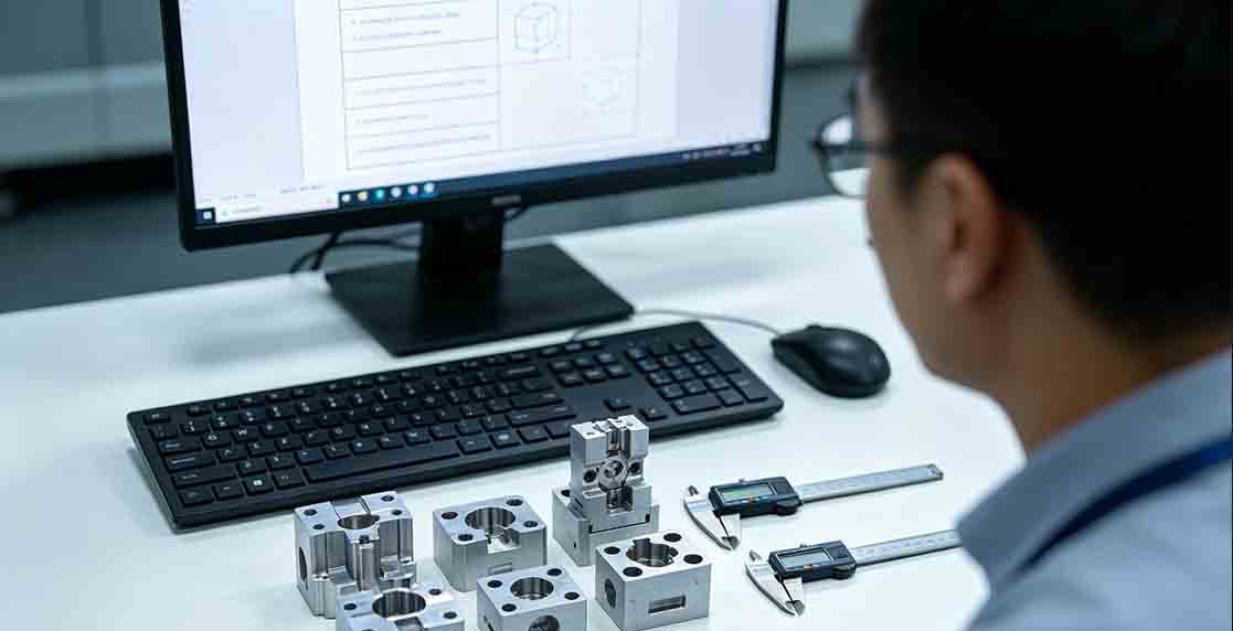
There is no universal “5-axis CNC machining price.”
A quote should be understood as the cost of an entire manufacturing system.
Cost Factor | Why It Matters |
Material | Raw material cost and machinability influence total cost |
Programming | Complex simultaneous machining requires more CAM engineering |
Machine time | Longer machining cycles increase cost |
Setup | Complex workholding and alignment add engineering time |
Tooling | Specialized cutters and tool holders can increase cost |
Inspection | Complex parts may require more measurement time |
Surface finishing | Anodizing, plating, polishing, passivation, coating, etc. add cost |
Quantity | Setup cost is distributed differently at different volumes |
Scrap risk | Difficult geometry may carry higher process risk |
Part complexity | More complex geometry increases programming and machining effort |
Fixture requirements | Custom fixtures can materially affect economics |
Suppose Supplier A uses a lower-cost machine but needs:
four setups, several fixtures, repeated alignment, long cutters, and multiple inspection stages.
Supplier B uses a more expensive 5-axis machine but can complete the major geometry in one primary setup.
The machine-hour rate of Supplier B may be higher.
But the total part cost can still be lower.
That is why comparing suppliers purely on hourly machining rates is often misleading.
A better comparison is:
material + programming + setup + machining + tooling + inspection + finishing + risk
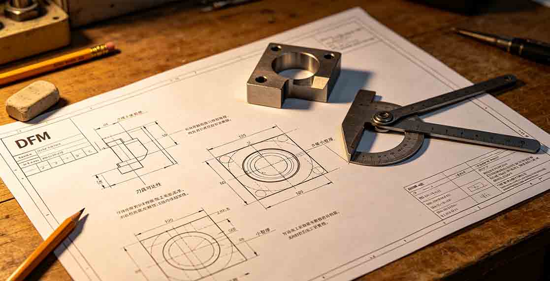
Good design can reduce cost before machining begins.
1. Design for Tool Access
Every surface should be evaluated from the cutter's perspective.
Ask:
Can the tool approach the feature?
Is the required orientation practical?
Is sufficient clearance available?
Does the holder collide before the cutter reaches the surface?
2.Avoid Unnecessarily Deep Pockets
Deep pockets may require long tools.
Long tools reduce rigidity and can increase: chatter, deflection, machining time, and tool wear.
3.Avoid Extremely Thin Walls
Thin walls can deform during machining.
A more rigid geometry may produce better process stability and improve dimensional consistency.
The exact minimum wall thickness should not be defined by a universal number because it depends on: material, size, unsupported length, tooling, fixture strategy, and tolerance.
4. Consider Internal Corner Radius
Milling cutters are round.
A sharp internal corner may therefore require: a smaller cutter, additional machining, EDM, or an alternative process.
A reasonable internal radius can reduce machining time.
5.Establish a Clear Datum Strategy
Datums are not simply dimensions on a drawing. They define how the part is located and inspected.
A good datum structure helps connect: design intent → fixturing → machining → inspection
6.Design Around Workholding
A feature may be technically machinable but practically difficult to fixture.
Think about: clamping surfaces, sacrificial areas, reference surfaces, access to critical faces, and fixture clearance.
7. Use Tolerance Hierarchy
Do not assign the tightest possible tolerance to every dimension.
Instead identify: critical functional dimensions, secondary dimensions, general dimensions, and cosmetic requirements.
This helps avoid paying for precision that the component does not actually need.
8. Specify Surface Finish Only Where Necessary
A polished surface should not be requested where a standard machined surface is functionally sufficient.
Surface requirements should reflect actual performance needs.
9. Plan Inspection Access
A critical feature that is difficult to inspect is also a manufacturing risk.
Designers and manufacturers should consider inspection accessibility before production begins.
Problem | Likely Cause | Process Factor | Corrective Direction |
Chatter | Insufficient rigidity | Tool length, holder, fixture, cutting parameters | Improve rigidity, shorten tool, optimize cutting strategy |
Poor surface finish | Unstable cutting or unsuitable toolpath | Tool orientation, step-over, spindle, tooling | Adjust toolpath and cutting conditions |
Dimensional variation | Thermal, fixture, tool, or machine variation | Workholding, heat, tool wear | Stabilize process and inspection |
Rotary positioning error | Rotary-axis condition or calibration issue | Machine kinematics | Verify rotary-axis performance and compensation |
Burrs | Tool geometry or exit condition | Cutting direction, tool wear | Optimize tool and toolpath |
Tool wear | Excessive heat or cutting load | Material, parameters, tool geometry | Adjust tooling and machining strategy |
Collision risk | Poor toolpath or insufficient clearance | CAM, holder, fixture | Perform simulation and verify setup |
Thermal drift | Heat accumulation | Machine environment, spindle, cycle length | Warm-up and stabilize process conditions |
Fixture-related error | Inadequate locating or clamping | Workholding | Improve datum and fixture strategy |
Chatter is rarely solved by simply lowering the feed rate.
The root cause may involve:
· cutter overhang,
· holder rigidity,
· workpiece support,
· fixture design,
· spindle behavior,
· or cutting conditions.
The best correction is usually a system-level correction.
Surface quality can be influenced by:
· toolpath spacing,
· tool orientation,
· tool wear,
· spindle runout,
· cutter geometry,
· cutting parameters,
· and material behavior.
Variation between parts may originate from:
· thermal change,
· fixture consistency,
· tool wear,
· machine behavior,
· measurement technique,
· or unstable material.
It is therefore dangerous to assume that dimensional variation automatically means “the machine is inaccurate.”
Rotary axes create additional geometric relationships that must be controlled.
For important applications, suppliers should be able to explain how machine performance is verified rather than making generic claims about “5-axis accuracy.”
ISO 230-2 provides standardized procedures for assessing the positioning accuracy and repeatability of numerically controlled linear and rotary axes.
Burr formation depends on:
· material,
· cutter geometry,
· tool wear,
· feed direction,
· feature geometry,
· and exit conditions.
Burr control should be treated as a machining-process issue rather than simply a manual deburring issue.
Tool wear changes cutting behavior over time.
For production parts, tool-life management becomes especially important because a part that passes initial inspection may drift later in a production run if tool condition is not controlled.
A supplier should be evaluated beyond the number of machines listed on its website.
Ask:
· What type of 5-axis machine is used?
· Is the rotary mechanism table-based, head-based, or hybrid?
· What is the usable working envelope?
A machine may be technically capable of five-axis motion but still be unsuitable for a large or tall component. Actual work envelope matters.
Understand:
· travel,
· orientation range,
· load capability,
· and how the rotary system interacts with the part.
Controller capability affects motion control, five-axis functions, and integration with CAM strategies.
A five-axis machine without strong CAM engineering is not automatically a strong five-axis manufacturing process.
Ask about:
· collision checking,
· post-processing,
· tool-axis control,
· simulation,
· and verification.
Evaluate whether the supplier has appropriate tools and holders for your material and geometry.
Ask how the part will be located, supported, and accessed.
The important question is not simply “Do you have inspection equipment?”
Ask: “How will you verify the critical features on this specific part?”
Titanium machining and POM machining are fundamentally different processes. Relevant material experience reduces technical risk.
Capacity should be evaluated relative to:
· part size,
· machining time,
· quantity,
· delivery requirements,
· and process complexity.
A factory's total machine count by itself does not tell you whether it can deliver your specific component reliably.
For projects requiring anodizing, passivation, plating, electropolishing, coating, or polishing, evaluate the supplier's ability to manage the complete process chain.
Depending on the project, you may require:
· dimensional inspection reports,
· material certificates,
· first article documentation,
· process records,
· or other traceability documents.
The exact requirement should be established from the customer's specification rather than assumed.
This is often underestimated. A supplier who identifies a problem during quotation is usually more valuable than a supplier who accepts every drawing without discussion.
Good engineering communication should address:
· tolerance conflicts,
· inaccessible features,
· material risks,
· fixture requirements,
· finishing constraints,
· inspection challenges,
· and production economics.
For international B2B buyers, manufacturing is only part of the supply chain.
The supplier should also be able to manage:
· drawing communication,
· technical clarification,
· packaging,
· documentation,
· delivery coordination,
· and international shipment requirements.
The correct strategy changes with quantity.
The priorities may be:
· engineering flexibility,
· rapid programming,
· minimal fixture investment,
· design validation,
· and fast iteration.
A 5-axis machine can be very useful when prototype geometry is complex.
The manufacturer begins to consider:
· repeatable fixture design,
· tool standardization,
· inspection efficiency,
· and process repeatability.
The balance shifts further toward:
· cycle-time optimization,
· tool-life management,
· fixture amortization,
· inspection automation,
· and stable process control.
This is where the assumption “5-axis is always best” becomes dangerous.
A high-volume component may be more economical using:
· 3-axis machining,
· 4-axis machining,
· CNC turning,
· mill-turn,
· dedicated fixtures,
· or automated production cells.
The best high-volume process is the one that minimizes total cost per acceptable part, not the one with the greatest axis count.
A mature CNC machining workflow should look something like this:
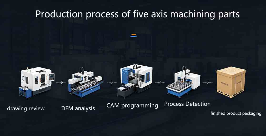
Drawing Review → DFM Analysis → Material Verification → Datum Strategy → Fixturing → CAM Programming → Machining → In-Process Inspection → Final Inspection → Finishing → Packaging
The first question is not:
“Can the machine cut this shape?”
It is:
“What does the drawing require the finished component to do?”
That determines which features are actually critical.
The engineer reviews:
· tool access,
· wall thickness,
· pocket depth,
· radii,
· tolerances,
· datums,
· threads,
· surface finish,
· and inspection requirements.
Material identity and condition should match the drawing or approved specification.
The manufacturing datum strategy should correspond logically to the design datum structure.
Fixture design should balance:
· rigidity,
· accessibility,
· repeatability,
· and cost.
The programmer selects the appropriate strategy. This may be:
· 3-axis,
· 3+2,
· or simultaneous 5-axis,
depending on the actual geometry.
Roughing, semi-finishing, and finishing strategies are selected according to the material and geometry.
Critical features may need to be checked before the entire component is completed. This is particularly important when later operations cannot recover from an early dimensional mistake.
The finished component is measured against the drawing and agreed inspection requirements.
Surface treatments are managed according to the final application.
The final stage should protect:
· machined surfaces,
· critical edges,
· threads,
· cosmetic surfaces,
· and functional features.
For an international buyer, packaging is part of manufacturing quality because damage during shipment can destroy the value created by a precise machining process.
For procurement teams, the machine itself is rarely the final objective.
The real objective is:
consistent parts delivered at an acceptable total cost and risk level.
A strong 5-axis supplier should therefore add value in several ways.
The supplier should identify manufacturing problems before production.
The supplier should select the appropriate combination of:
· machine,
· tool,
· fixture,
· CAM strategy,
· and inspection method.
The supplier should be able to define how critical requirements will be verified.
The supplier should optimize not only machining rate, but also:
· setup,
· tooling,
· material usage,
· scrap risk,
· inspection,
· and finishing.
The supplier should provide predictable communication and delivery across the entire manufacturing process.
1. What is 5-axis CNC machining?
5-axis CNC machining uses three linear axes plus two rotary axes to position and orient a cutting tool relative to a workpiece. Its primary advantage is improved access and tool orientation for complex geometry.
2. What are the five axes in CNC machining?
The three linear axes are X, Y, and Z. The remaining two are rotary axes selected from A, B, and C.
3. Is 5-axis CNC more accurate than 3-axis CNC?
Not automatically. Five-axis machining can reduce setup-related variation on suitable multi-sided parts, but rotary-axis accuracy, machine condition, fixturing, thermal stability, tooling, CAM, material, and inspection all affect the final result.
4. What is the difference between 3+2 and simultaneous 5-axis machining?
3+2 machining uses the rotary axes to orient the cutting tool or workpiece and then performs a conventional cutting operation. Simultaneous 5-axis machining coordinates multiple axes during the cutting motion itself.
5. What materials can be machined with 5-axis CNC?
A wide range of metals and engineering plastics can be machined, including aluminum, stainless steel, carbon steel, tool steel, titanium, brass, copper, Inconel, PEEK, POM, nylon, and PEI. The correct cutting strategy depends on the individual material grade and condition.
6. What parts require 5-axis CNC machining?
Parts are good candidates when they have complex surfaces, multiple angled faces, deep features, difficult tool access, or important features spread across multiple surfaces. Not every complex-looking part technically requires five axes.
7. Is 5-axis CNC more expensive?
The machine itself may carry a higher processing cost, but total part cost depends on programming, setups, tooling, fixtures, inspection, machining time, quantity, and scrap risk. A higher machine-hour rate can sometimes produce a lower total part cost.
8. Can 5-axis CNC reduce machining setups?
Yes. One of its major advantages is the ability to access multiple surfaces from fewer physical setups. However, the final setup count still depends on the part geometry and workholding design.
9. Is 5-axis CNC suitable for mass production?
Yes, but it is not automatically the best choice. For high-volume production, process economics should be compared against 3-axis, 4-axis, turning, mill-turn, and other possible production methods.
10. How much does 5-axis CNC machining cost?
There is no universal price. The cost depends on material, part complexity, programming, machine time, setup, tooling, fixture requirements, inspection, finishing, quantity, and production risk.
11. What is the difference between 4-axis and 5-axis CNC?
A 4-axis machine adds one rotary axis to the three linear axes. A 5-axis machine adds a second rotary degree of freedom, providing more flexible tool orientation and access to complex surfaces.
12. How do I choose a 5-axis CNC machining supplier?
Evaluate machine configuration, machine envelope, rotary-axis architecture, CAM capability, tooling, workholding, inspection, material experience, production capacity, surface finishing, quality documentation, engineering communication, and international supply-chain experience.
Ready to transform your CAD file into a custom part? Upload your design to get a free, precise quote.
Get Your Instant Quote