






Can FR4 Be CNC Machined? How to Prevent Delamination and Fiber Burrs
Published on Sunday, 01. November 2026
Content Guide:Learn how to CNC machine FR4 without delamination and fiber burrs. Compare carbide, diamond-coated, and PCD tooling, set feeds and speeds, and control machining costs.
Yes — FR4 can be CNC machined. CNC milling, routing, drilling, turning, and engraving can all produce functional FR4 components when the tooling, workholding, and cutting conditions are matched to the material. FR4 is a glass-fiber-reinforced epoxy laminate, and its abrasive reinforcement and layered construction create specific risks: delamination, fiber burrs, edge chipping, tool wear, and heat damage. These risks are controllable through correct tool selection, stable support, controlled feed and speed, effective dust extraction, and inspection that goes beyond dimensional accuracy.
This guide covers the process fundamentals. For production sourcing, see FR4 CNC machining services.
FR4 is machinable with conventional CNC equipment when the process is developed for abrasive glass-fiber composites.
Delamination is a laminate-integrity problem caused by excessive cutting force, insufficient support, unsuitable tool geometry, or tool wear.
Fiber burrs are not metal burrs. Glass fibers fracture, pull out, or remain protruding; conventional metal deburring methods are often inappropriate.
Tooling drives both quality and cost. Carbide, diamond-coated carbide, and PCD tooling each have a place depending on volume and edge-quality requirements.
Inspection must cover edge integrity, delamination, fiber protrusion, hole quality, and copper-layer damage — not just external dimensions.

FR4 is a glass-fiber-reinforced epoxy laminate used in printed circuit boards (PCBs) and electrical insulation components. It consists of woven electrical-grade glass fabric, a cured epoxy resin matrix, flame-retardant chemistry in applicable formulations, and optional copper cladding in PCB laminate products. The glass fabric provides mechanical reinforcement; the epoxy binds the structure and contributes to electrical insulation and dimensional stability.
FR4 is a thermoset composite, not a thermoplastic. Once cured, its epoxy matrix does not melt and reform like ABS, POM, or nylon. Excessive machining heat causes resin degradation, surface discoloration, or thermal damage rather than controlled melting.
The difficulty comes from the interaction between two materials with different mechanical behavior:
Glass fibers are abrasive against cutting edges, causing rapid tool wear and producing fractured or protruding fibers.
Epoxy resin holds the fibers together but can crack, chip, or suffer thermal damage under unsuitable cutting conditions.
The laminated, woven construction creates a directional, layered structure. Cutting forces can damage the resin–fiber interface or separate adjacent layers.
Machining FR4 therefore requires attention to both material removal and the integrity of the remaining laminate.
Different FR4 products have different resin systems, glass constructions, thicknesses, thermal characteristics, and electrical properties. For example, one commercially available FR4 grade (Isola IS410) is documented at a glass-transition temperature (Tg) of 180°C and a UL 94 V-0 flammability rating. These values apply to that grade only and must not be assumed for other FR4 products. [1]
For procurement and machining, engineers should check:
Manufacturer and material grade.
Applicable IPC-4101 specification sheet, where relevant. [2]
Laminate thickness and thickness tolerance.
Glass construction and resin system.
Glass-transition temperature.
Flame-retardant classification and supporting documentation.
Copper-clad or unclad construction.
Material condition and supplier traceability.
IPC-4101 provides requirements for laminate and prepreg base materials used primarily in rigid and multilayer printed boards; its specification sheets distinguish material constructions and performance requirements. A machining process developed for one FR4 product should not be transferred to another without checking the material documentation and running suitable trials.
FR4 can be manufactured into different geometries through several CNC operations. The appropriate process depends on part geometry, thickness, dimensional requirements, and production quantity.
CNC operation | Typical applications | Main machining concern |
|---|---|---|
CNC milling | Pockets, slots, mounting surfaces, component housings | Edge damage, fiber pull-out, delamination |
CNC routing | Profiles, contours, thin panels, PCB outlines | Top- and bottom-edge quality |
CNC drilling | Mounting holes, electrical installation holes, fixtures | Entry and exit delamination |
CNC turning | Custom cylindrical insulating components | Tool wear, surface integrity, edge chipping |
CNC engraving | Identification marks, shallow grooves, component markings | Surface damage and fiber exposure |
CNC milling and routing are commonly used to produce custom FR4 components. The cutting tool removes material through repeated cutting engagement, but the reinforced glass fabric creates an abrasive cutting environment. Unlike machining homogeneous aluminum, the cutting edge encounters glass fibers and epoxy resin with different mechanical characteristics.
This can result in fiber fracture, resin chipping, surface cavities, uneven edges, localized delamination, and increased cutting-edge wear. A suitable cutter should produce controlled material separation rather than repeatedly pushing and tearing the reinforced structure.
For related process capabilities, see CNC milling services.
Drilling introduces a different problem. A rotating drill moves through the laminate while its cutting edges generate axial thrust and cutting forces. If the material is inadequately supported, these forces can separate the reinforcement layers, especially near the entry and exit surfaces.
Two commonly discussed forms of drilling-induced delamination are:
Peel-up delamination: damage near the drill-entry surface as the cutting action lifts or separates the upper laminate layers.
Push-down delamination: damage near the exit surface when drilling thrust pushes the remaining laminate layers apart.
Both compromise hole quality and reduce the integrity of the finished component. Experimental research on glass-fiber-reinforced epoxy composites has identified feed rate, tool geometry, cutting speed, laminate thickness, and drilling forces as important factors influencing delamination. The exact findings and optimal parameters depend on the tested composite and should not be transferred directly to every FR4 product. [3][4]
For drilling-specific capabilities, see CNC drilling services.
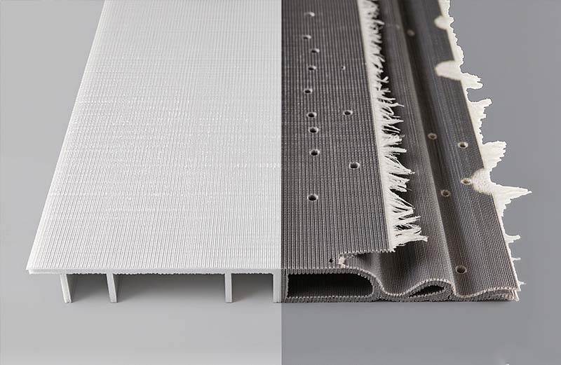
Delamination occurs when adjacent reinforced layers separate or when damage develops along the interface between reinforcement and resin. It is one of the most important quality concerns in FR4 CNC machining because it affects structural integrity, electrical performance, and moisture resistance — not just appearance.
When a cutting tool encounters a glass-fiber bundle, it must shear or fracture the reinforcement while removing the surrounding resin. If the tool generates excessive force or the laminate lacks adequate support, the load propagates through the material rather than being confined to the intended cutting region. This creates cracks between reinforced layers, separation around drilled holes, cracked or lifted laminate edges, and localized structural damage. In electrical components, delamination may also expose areas that require protection from moisture, contamination, or mechanical damage.
Cause | How it creates damage | Recommended corrective action |
|---|---|---|
Excessive feed per tooth | Increases cutting force and drilling thrust | Optimize feed based on tool geometry and material |
Worn cutting tools | Produces rubbing, tearing, and unstable cutting forces | Establish tool-wear inspection and replacement criteria |
Insufficient workpiece support | Allows laminate layers to flex during cutting | Use full-area support and appropriate backing |
Unsuitable tool geometry | Pulls, pushes, or fractures fibers rather than cutting cleanly | Select composite-appropriate cutting geometry |
Thermal overload | Damages or weakens the epoxy matrix | Control heat generation, engagement, and chip removal |
Important distinction: lowering feed rate is not automatically the correct solution. An excessively low feed can cause rubbing rather than efficient cutting, increasing localized heat and tool wear. The objective is a stable cutting condition that balances cutting force, chip formation, temperature, and tool life.
Preventing delamination requires controlling several variables together. Tool selection alone cannot compensate for inadequate workholding, poor support, or inappropriate cutting conditions.
Glass fibers are abrasive, and tool wear can rapidly change the effective cutting geometry even when the machine continues to operate normally. Tooling should be selected with attention to hardness, wear resistance, sharpness, and the manufacturer’s recommendations for glass-reinforced composites.
Tool type | Characteristics | Typical suitability |
|---|---|---|
Solid carbide tooling | Good wear resistance and suitable cutting-edge strength | General FR4 milling, routing, and drilling |
Diamond-coated carbide tooling | Enhanced abrasive-wear resistance, depending on coating and tool design | Applications requiring improved tool-life consistency |
PCD tooling | High abrasive-wear resistance; potential for extended production life | Longer production runs and demanding repetitive applications |
Conventional HSS tooling | Generally less suitable for sustained machining of abrasive glass-fiber composites | Limited use where material and operation permit |
Research comparing high-speed steel and cemented carbide drills in glass-fiber-reinforced epoxy found substantially greater wear with HSS under the studied conditions. [5] This supports the preference for suitable carbide tooling in repeated composite drilling, although the actual tool specification should be selected for the specific application. Tool-life benefit from diamond-coated or PCD tooling depends on coating quality, laminate abrasiveness, cutting parameters, and tool geometry; validate by trial on the actual FR4 grade.
Practical recommendation: do not evaluate tooling on purchase price alone. Compare cost per acceptable finished part, including tool replacement, setup interruptions, rework, and inspection.
For CNC routing and milling, flute geometry determines how the tool engages the laminate and removes material. Three configurations are particularly relevant:
Tool geometry | Potential advantage | Limitation |
|---|---|---|
Upcut | Helps transport chips away from the cutting area | May lift or damage fibers near the upper surface |
Downcut | Can help restrain material near the upper surface | May compress chips into the cutting area and increase heat |
Compression | Combines opposing flute directions to support both surface regions | Requires appropriate tool geometry and engagement for the material thickness |
A compression cutter can be useful when both top- and bottom-edge quality matter, but it is not automatically the best tool for every FR4 part. Its effectiveness depends on laminate thickness, flute geometry, cutting depth, workpiece support, and chip evacuation. The up/down transition must sit at or below the finished surface; if the depth of cut does not engage the correct flute zone, edge quality can degrade.
For drilling, point geometry and cutting-edge condition also influence axial thrust and hole damage. The best approach is to compare resulting edge and hole quality on representative material coupons rather than relying on a general-purpose cutter recommendation.
Feed rate and spindle speed influence cutting forces, heat generation, chip formation, and tool wear. The relationship between feed rate and cutting load is particularly important when machining fiber-reinforced materials. An excessively aggressive feed may increase mechanical loading and promote delamination; an excessively conservative feed may cause rubbing, poor chip formation, and unnecessary heat. The relationship is not identical for drilling, milling, and routing.
For milling and routing: avoid excessive tool engagement; maintain a consistent feed; prevent prolonged rubbing or dwell; use suitable chip evacuation; check tool wear during repeated cutting.
For drilling: choose a drill geometry suitable for the laminate; control axial thrust; support the exit surface; verify both entry and exit hole quality; review hole geometry and tool condition when damage occurs.
Cutting speed should be determined using the tool manufacturer’s recommendations and verified through actual machining trials. There is no universally reliable RPM and feed-rate combination for all FR4 sheets, tool diameters, flute configurations, and laminate constructions.
Workholding is one of the most effective ways to reduce machining damage. When drilling or cutting thin FR4 panels, the material can flex if the underside is not adequately supported. A suitable sacrificial backing plate can:
Support the exit surface during drilling.
Reduce unsupported laminate movement.
Improve consistency between parts.
Protect the machine table.
Reduce damage during breakthrough.
For thin FR4 panels, distributed support is generally preferable to a few isolated clamping points. For contour machining, the fixture should prevent vibration without creating excessive localized pressure. When using vacuum workholding, check that the panel seals adequately and remains stable throughout machining.
FR4 does not melt and flow like an ordinary thermoplastic, but excessive heat can still damage its epoxy matrix. Potential signs of thermal problems include discoloration, resin degradation, unusual cutting odors, changes in edge appearance, and increased tool wear.
Effective chip removal is important because abrasive particles left in the cutting zone interfere with the tool–workpiece interaction. Dry machining with suitable local dust extraction is a common approach for FR4 routing and milling. Wet machining should be evaluated against the specific laminate, machine, downstream cleaning requirements, and any moisture-control requirements; it should not be assumed suitable for every electrical laminate application.
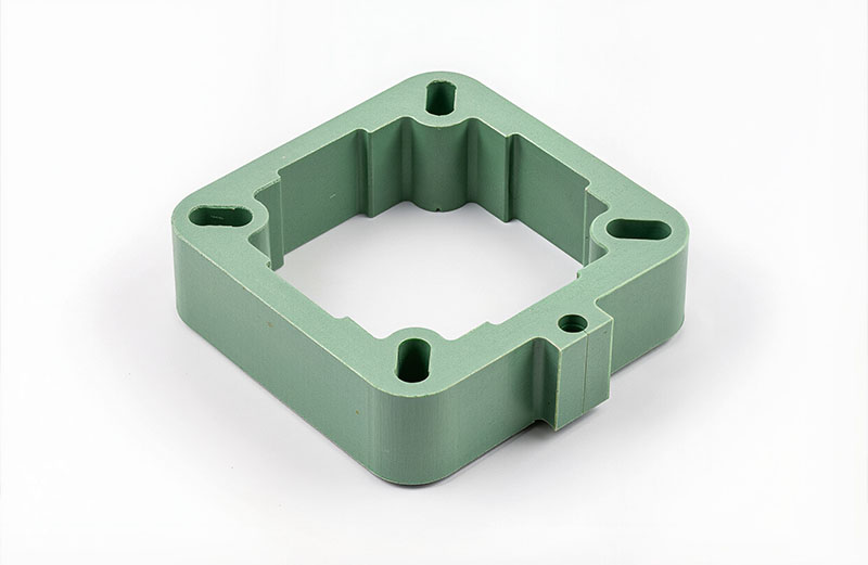
Fiber burrs are a different problem from conventional metal burrs. When machining aluminum, burrs generally result from plastic deformation of ductile metal. FR4 behaves differently: its glass reinforcement can fracture, pull out, or remain partially attached to the epoxy matrix. The resulting defects include protruding glass fibers, frayed edges, fiber bundles sticking out from the machined surface, localized epoxy chipping, and small cavities where fibers have pulled out. These conditions are better understood as fiber breakout, pull-out, and edge damage rather than ordinary metal burr formation.
The cutting tool must separate the glass reinforcement and resin. If the cutting edge is sharp and the material is adequately supported, fibers can be cut more consistently. If the edge becomes worn or the laminate vibrates during cutting, glass fibers may fracture irregularly, and the surrounding resin may break away, leaving portions of the reinforcement exposed. The result is an uneven edge with protruding fiber strands.
Method | How it works | Engineering benefit |
|---|---|---|
Use sharp composite-appropriate cutters | Reduces uncontrolled tearing and rubbing | Cleaner fiber separation |
Maintain stable workholding | Limits vibration and panel movement | More consistent edge geometry |
Use appropriate flute geometry | Controls cutting engagement and chip evacuation | Reduced surface breakout |
Optimize cutting engagement | Limits excessive cutting forces | Reduced fiber pull-out |
Apply a light finishing pass where appropriate | Removes minor residual edge damage | Improved dimensional and visual finish |
A finishing pass can improve edge consistency, but it should not be used to hide severe delamination. The objective is to prevent damage during the primary machining operation.
Yes. Minor protruding fibers can sometimes be removed through controlled finishing: fine abrasive finishing, controlled edge brushing, precision hand finishing, suitable mechanical deburring tools, or specialized edge-finishing processes. However, finishing must be matched to the part’s requirements. Aggressive sanding can remove additional resin, expose more glass reinforcement, round critical edges, or reduce dimensional accuracy. For electrical insulation components, surface integrity and cleanliness may matter as much as visual appearance.
Important: post-machining finishing should not be treated as a substitute for preventing delamination or excessive fiber breakout during CNC machining.
There is no universal CNC machining recipe for FR4. Correct values depend on the actual material and cutting system. The following variables should be considered during process development.
Parameter | What it controls | Risk when poorly selected |
|---|---|---|
Spindle speed | Cutting velocity and thermal conditions | Excessive heat or ineffective cutting |
Feed rate | Tool movement relative to material removal | Excessive forces or rubbing |
Feed per tooth | Material engagement per cutting edge | Poor chip formation or increased cutting load |
Axial depth of cut | Tool engagement through laminate thickness | Excessive thrust and edge damage |
Radial engagement | Tool contact with the material | Higher forces and vibration |
Tool diameter | Cutting geometry and tool stiffness | Deflection or unsuitable access |
Flute count | Cutting-edge engagement and chip space | Inadequate chip evacuation |
Tool condition | Sharpness and effective cutting geometry | Fiber tearing and inconsistent edges |
Workholding | Material movement during machining | Vibration and delamination |
Feed per tooth is useful when comparing cutting conditions for different spindle speeds and flute counts. Its basic relationship is:
fz = Vf / (n × z)
Where fz = feed per tooth; Vf = programmed feed rate; n = spindle speed in revolutions per minute; z = number of cutting flutes.
This relationship helps engineers understand how feed and spindle speed combine to determine the material engagement of each cutting edge. However, the calculated value is not an FR4-specific recommended setting; it must be evaluated against tool geometry, material construction, machining operation, and the manufacturer’s cutting recommendations.
A controlled trial is more reliable than applying an unrelated cutting recipe.
Confirm the FR4 manufacturer, grade, thickness, and material condition.
Select tooling intended for abrasive glass-fiber-reinforced materials.
Establish stable workholding and adequate support.
Begin with the tool manufacturer’s recommended cutting range.
Machine a representative test coupon.
Inspect entry and exit surfaces, edges, hole quality, and dimensions.
Review tool wear and signs of thermal damage.
Adjust the process based on the observed defect.
Record the approved setup and inspection results for production.
Change one important variable at a time where practical. This makes it easier to identify the actual cause of improvement or deterioration.
FR4 is not necessarily the best material for every insulating or structural component. Its advantages are associated with its reinforced laminate construction, electrical properties, and availability in suitable grades. Its abrasive reinforcement introduces machining challenges that do not exist to the same degree in many unreinforced plastics.
Material | Main strengths | CNC machining characteristics | Potential limitations | Typical selection context |
|---|---|---|---|---|
FR4 | Glass reinforcement, electrical insulation, mechanical stiffness | Abrasive; requires suitable tooling and edge control | Fiber breakout, tool wear, delamination | Electrical insulation plates, PCB substrates, fixtures |
G10 | Glass-fabric epoxy laminate with substantial mechanical reinforcement | Similar composite machining considerations | Grade-specific electrical and flame-retardant documentation must be checked | Industrial insulating and mechanical components |
G11 | Glass-fabric epoxy laminate designed for improved elevated-temperature performance in relevant grades | Similar abrasive cutting concerns | Higher-grade material availability and cost considerations | Applications needing elevated-temperature capability |
POM | Low friction, good dimensional stability in suitable applications, easy machining | Generally straightforward CNC machining | Not equivalent to FR4’s glass reinforcement or flame-retardant laminate characteristics | Precision mechanical parts and sliding components |
PEEK | High-performance thermoplastic with good mechanical and thermal properties in suitable grades | Generally machinable, but heat and dimensional behavior require control | Higher material cost; filled grades can also be abrasive | High-performance industrial components |
Phenolic laminate | Electrical insulation and established industrial laminate applications | Depends strongly on reinforcement and resin construction | Different mechanical, thermal, and moisture behavior | Electrical and mechanical insulation applications |
Material-selection principle: choose the material based on the final component’s functional requirements, not solely on machining difficulty or raw-material price. For related material options, see the engineering plastic materials library, PEEK CNC machining, and POM CNC machining.
High-quality FR4 components require control of several connected factors.
Different laminate manufacturers and product grades can have different reinforcement constructions, resin systems, and thickness tolerances. Variation in the starting stock may affect cutting behavior, tool wear, dimensional consistency, surface appearance, flatness, and edge integrity. For production components, using consistent and documented material grades helps reduce process variation.
Tool and workpiece vibration can cause unstable cutting engagement, contributing to uneven edge quality, fiber breakout, surface irregularities, dimensional variation, and premature tool wear. A stable machine, suitable tooling, and a rigid fixture help maintain consistent contact between the cutter and laminate.
FR4 components may require closely controlled mounting holes, slots, pockets, and installation interfaces. However, the dimensional result is influenced by more than machine positioning accuracy: initial sheet thickness variation, panel flatness, fixture deformation, tool deflection, thermal effects, material anisotropy, and machining sequence all matter. Tight tolerances should therefore be assigned to functional dimensions rather than applied indiscriminately to every surface.
FR4 quality inspection should evaluate more than overall dimensions.
Inspection item | What should be checked | Potential inspection method |
|---|---|---|
External dimensions | Length, width, and thickness | Caliper, micrometer, CMM |
Hole quality | Diameter, position, and edge condition | Pin gauges, vision measurement, CMM |
Edge integrity | Fiber breakout, delamination, chipping | Visual inspection and magnification |
Surface condition | Scratches, cavities, resin damage | Visual inspection |
Flatness | Panel deformation and surface variation | Surface plate and suitable measurement system |
Copper condition | Copper-layer integrity, where applicable | Visual inspection and electrical testing |
Material identification | Grade and supplier documentation | Certificate and material traceability review |
For high-reliability components, the inspection plan should define acceptable edge defects and dimensional limits before production begins. A component can meet its external dimensions while still having unacceptable internal or edge damage. Where the application is critical, additional inspection methods such as microscopic examination or cross-sectional analysis may be justified.
For quality-system context, see precision machining quality control.
Defect | Possible root cause | Recommended solution |
|---|---|---|
Delamination around drilled holes | Excessive thrust, worn drill, inadequate support | Review drill geometry, feed, tool condition, and backing |
Fiber burrs along edges | Dull cutter, unsuitable flute design, material vibration | Use sharper composite tooling and improve support |
Rough machined surfaces | Tool wear, unstable cutting, poor engagement | Review tool condition and cutting parameters |
Burned or discolored edges | Excessive local heat or rubbing | Review speed/feed relationship, tool condition, and chip evacuation |
Uneven hole diameter | Tool runout, deflection, or unstable workholding | Check spindle/tool condition and fixture rigidity |
Excessive tool wear | Abrasive reinforcement and unsuitable tooling | Consider suitable carbide, coated carbide, or PCD tooling |
Bottom-surface breakout | Inadequate exit support during machining | Add a suitable sacrificial backing plate |
Panel deformation | Inappropriate clamping or uneven support | Improve distributed support and machining sequence |
Exposed or damaged copper | Incorrect cutting depth, fixture interference, or poor routing process | Review copper layout, machining allowance, and toolpath |
When delamination occurs repeatedly, replacing the cutting tool may not solve the underlying problem. A more useful investigation follows the defect pattern:
Damage mainly at the hole entry: investigate entry-layer support, drill geometry, cutting-edge condition, and initial drilling engagement.
Damage mainly at the hole exit: investigate thrust force, backing support, and drilling breakthrough conditions.
Damage along milled edges: investigate tool wear, toolpath, cutting engagement, laminate support, and cutter geometry.
Defect appears after several production cycles: investigate changes in tool wear, material batches, fixture condition, and machining stability.
This approach is more effective than repeatedly changing CNC parameters without identifying the actual mechanism.
The cost of CNC machining FR4 is determined by material, processing time, tooling, workholding, inspection, and production quantity. It is not simply a question of how much FR4 sheet is consumed.
Cost factor | How it affects the quotation | Procurement consideration |
|---|---|---|
FR4 material grade | Different grades and documentation requirements affect material cost | Specify the exact grade |
Material thickness | Influences cutting engagement and machining time | Confirm finished thickness and tolerance |
Part geometry | Complex pockets and contours require more machining | Optimize design for manufacturability |
Number of holes | Drilling time and tool wear can increase | Review hole size and quantity |
Machining tolerance | Tight tolerances require more careful machining and inspection | Identify critical dimensions |
Tool consumption | Abrasive glass reinforcement affects cutter life | Ask about tooling strategy |
Workholding | Thin or irregular panels may need dedicated fixtures | Review whether tooling costs are necessary |
Inspection | Detailed edge, hole, and dimensional inspection increases processing effort | Define inspection requirements |
Production quantity | Setup and fixture costs are distributed across the order | Compare prototype and batch pricing |
CNC machining can be economical for prototypes because it avoids dedicated molding or punching tools. It is particularly useful when the design is still changing, the order quantity is limited, complex holes and pockets are required, the component needs evaluation before full production, or a custom geometry is difficult to produce through standard fabrication methods. For repetitive, relatively simple FR4 shapes, dedicated cutting, punching, or other production methods may be more economical than machining every feature individually. For more complex parts, CNC machining may remain suitable because it offers design flexibility and avoids some dedicated tooling investments. A production quotation should consider both the initial setup cost and the cost per acceptable finished component.
For a project-specific quotation, request a CNC machining quotation.
Thin FR4 walls and narrow features can be difficult to machine consistently because the material can vibrate or flex under cutting forces. Where possible, use sufficient wall thickness, avoid excessively narrow unsupported features, design stable mounting and fixture interfaces, and consider the machining sequence before finalizing the geometry.
Small holes may require specialized tools and more careful process control. Engineers should review hole diameter, hole depth, hole-to-edge distance, hole spacing, required positional tolerance, and entry/exit surface requirements. Very small holes or high-density hole patterns may require specialized equipment and a different production approach.
An engineering drawing should specify whether the component requires clean-cut edges, no visible delamination, controlled fiber protrusion, a defined edge break, and specific surface-finish requirements. A simple statement such as “burr-free” may be insufficient for glass-fiber-reinforced laminates. For critical parts, the drawing or inspection specification should define the acceptable degree of fiber exposure and edge damage.
Some FR4 products contain copper foil. In these cases, the manufacturing process must consider both the epoxy-glass laminate and the copper layer. Potential concerns include copper foil lifting, smearing at machined edges, unintended exposure of copper, electrical clearance requirements, and damage to adjacent conductive features. PCB routing and machining should therefore be planned using the actual copper layout and electrical design requirements.
For overseas buyers, choosing an FR4 machining supplier requires more than checking whether the company operates CNC milling machines. FR4 requires experience with abrasive composite materials and a quality-control process capable of detecting defects that may not be obvious during dimensional inspection.
Evaluation area | Questions to ask |
|---|---|
Material experience | Does the supplier regularly process FR4 and other glass-fiber-reinforced laminates? |
Tooling | What tooling materials and geometries are used for FR4? |
Machining processes | Can the supplier handle milling, routing, drilling, and complex profiles? |
Workholding | How are thin panels and delicate components supported? |
Tool management | How is tool wear monitored and controlled? |
Edge quality | How are delamination and fiber burrs inspected? |
Dimensional inspection | Can the supplier measure holes, profiles, thickness, and critical tolerances? |
Material traceability | Can the supplier provide material identification and relevant documentation? |
Production capability | Can the supplier maintain repeatability across the requested quantity? |
Communication | Can engineers review drawings and identify manufacturing risks before production? |
For a demanding FR4 component, sample approval is an effective way to reduce procurement risk. The sample should be evaluated for overall dimensions, hole position and diameter, edge quality, fiber protrusion, delamination, flatness, material identification, and functional assembly requirements. The approved sample and inspection criteria can then form the basis of the production acceptance process.
To obtain a meaningful FR4 CNC machining quotation, buyers should provide: (1) 2D engineering drawing; (2) 3D CAD model, if available; (3) exact FR4 grade or material requirement; (4) material thickness; (5) required quantity; (6) critical dimensions and tolerances; (7) hole and surface-finish requirements; (8) edge-quality requirements; (9) material certification or traceability requirements; and (10) expected production schedule. The more accurately the engineering requirements are defined, the easier it is for the supplier to identify potential problems before machining begins.
The best manufacturing strategy can change significantly as the order quantity increases.
Consideration | Prototype production | Small and medium batches | Larger production runs |
|---|---|---|---|
Primary objective | Verify geometry and function | Maintain repeatability | Improve production consistency and unit economics |
Tooling | General-purpose suitable composite tooling | Dedicated tooling strategy where justified | Optimized tool life and replacement planning |
Workholding | Flexible fixtures | Repeatable fixtures | Dedicated production fixtures |
Inspection | Detailed first-piece inspection | First-piece and process checks | Defined inspection plan and sampling strategy |
Material control | Confirm prototype-grade material | Verify batch consistency | Material traceability and incoming inspection |
Cost priority | Minimize initial setup | Balance setup and machining cost | Optimize total manufacturing cost |
CNC machining enables engineers to check part geometry, assembly fit, mounting holes, and functional performance before committing to larger production quantities. It also helps identify problems such as excessively thin walls, difficult-to-machine slots, unacceptable edge quality, hole-position errors, insufficient material support, and interference with adjacent components. The design can then be modified before production.
Once the design is approved, consistency becomes the priority. A successful prototype does not automatically guarantee stable batch manufacturing. The supplier should establish approved material specifications, defined tool replacement criteria, repeatable workholding, controlled machining parameters, inspection methods, production records, and traceability where required. This is particularly important for FR4 components used in electrical assemblies, where small dimensional or material variations may influence final assembly.
FR4 machining produces dust containing material derived from the glass reinforcement and cured resin system. Dust exposure should be considered during milling, drilling, routing, grinding, and finishing. The hazards depend on the specific laminate formulation and the machining process.
For example, a commercially available FR4 laminate safety data sheet (SDS) — such as the Isola IS410 SDS — recommends adequate ventilation, local exhaust ventilation where dust is generated, suitable eye protection, and appropriate dust-control procedures. It also advises against using compressed air or dry sweeping to clean accumulated dust. [6]
Recommended workplace controls include:
Use suitable local dust extraction at the machining point.
Prevent unnecessary accumulation of laminate dust.
Use an industrial vacuum with an appropriate high-efficiency filtration system.
Avoid blowing dust away with compressed air.
Follow the actual product safety data sheet.
Use suitable eye protection and other PPE based on the risk assessment.
Apply applicable workplace exposure-control procedures.
For UK facilities, the control strategy should also be assessed under the relevant COSHH requirements. Dust extraction is not merely a housekeeping issue; it is part of maintaining a controlled and repeatable machining environment.
Yes. FR4 can be machined using CNC milling, routing, drilling, turning, and engraving. The material’s glass reinforcement makes tooling selection and cutting-force control important; suitable composite tooling, stable workholding, and effective dust extraction are required.
FR4 is more challenging than many unreinforced engineering plastics because its glass fibers are abrasive and its laminated construction can be damaged by excessive cutting forces. Difficulty depends on material grade, thickness, part geometry, tool condition, and required surface quality.
Delamination can result from excessive machining forces, high drilling thrust, insufficient workpiece support, inappropriate cutting geometry, tool wear, or thermal damage. The most effective solution is to identify the defect’s location and mechanism before changing cutting parameters (see §9.1).
Use suitable composite drilling tools, maintain proper workpiece support, control axial thrust, and establish appropriate cutting conditions. A sacrificial backing plate can help reduce exit-side damage by supporting the material during breakthrough.
FR4 contains woven glass reinforcement. During machining, these fibers may fracture, pull out, or remain partially attached to the surrounding epoxy resin, producing protruding fibers or frayed edges.
Suitable solid carbide, diamond-coated carbide, or PCD tooling may be used depending on the operation, production volume, material, and required finish. Tool geometry and cutting-edge condition are as important as tool material. See §4.1 for selection boundaries.
Not always. Carbide tooling may be appropriate for many applications. Diamond-coated or PCD tooling may become economically attractive when abrasive wear and repeated production justify the additional tooling investment. The decision should consider tool life and cost per acceptable part.
Yes, depending on component geometry, production quantity, and cost targets. For repeated production, manufacturers should optimize tooling, workholding, tool replacement, machining parameters, and inspection procedures. Other production methods may be more economical for simpler high-volume shapes (see §10 and §13).
Machining can generate airborne dust and particles from the glass-fiber and resin laminate. The appropriate precautions depend on the material’s safety data sheet and workplace risk assessment. Local exhaust ventilation, controlled cleaning, and suitable PPE should be incorporated into the process. See §14 for details.
The price depends on material grade, thickness, component geometry, machining time, drilling requirements, tooling wear, workholding, inspection, and order quantity. A technical drawing and material specification are necessary for a meaningful quotation. See §10 for the cost-factor breakdown.
FR4 can be CNC machined successfully, but consistent results depend on understanding how glass reinforcement and epoxy resin respond to machining forces, cutting geometry, and heat. The most important priorities are selecting appropriate wear-resistant tooling, maintaining stable workholding, controlling feed and cutting engagement, supporting the laminate during drilling, and inspecting edge integrity.
For demanding components, engineers should validate the machining process using representative material samples before committing to batch production. The objective is not simply to machine FR4 to the correct dimensions; it is to produce components with the required dimensional accuracy, electrical functionality, edge quality, and structural integrity throughout the intended production quantity.
For engineers and procurement teams sourcing custom FR4 components, a supplier’s experience with abrasive composite machining, process control, and inspection capability should be considered alongside the quotation price. To discuss a specific project, explore FR4 CNC machining services or request a quotation.

Ready to transform your CAD file into a custom part? Upload your design to get a free, precise quote.
Get Your Instant Quote